
Stretchable electrically-conductive circuit and manufacturing method therefor

a technology of electrically conductive circuits and stretchable sheets, applied in the direction of conductive layers on insulating supports, instruments, conductors, etc., can solve the problems of preventing the popularization of stretchable electrical conductors in sports science and medicine, complicated manufacturing process, and high final product cost, so as to improve the flexibility of elastomer sheets, improve the flexibility, and improve the effect of stretchability

Active Publication Date: 2019-08-20
NAT INST OF ADVANCED IND SCI & TECH
View PDF25 Cites 0 Cited by
  • Summary
  • Abstract
  • Description
  • Claims
  • Application Information

AI Technical Summary

Benefits of technology

The present invention provides a cost-effective and stretchable electrically-conductive circuit that can bend and stretch without compromising its flexibility. The circuit is made by adsorbing electrically-conductive fiber materials onto an elastomer sheet. This results in a wiring region that maintains electrical continuity when the sheet is stretched or bent. The circuit can be used as a stretch sensor or capacitive pressure sensor. The method of manufacturing the circuit involves attaching the electrically-conductive fiber materials to the elastomer sheet using an adhesive layer, which ensures mutual electrical continuity between the fiber materials.

Problems solved by technology

Although these materials are expensive, it is necessary to extremely enhance contents of these materials in order to obtain sufficient electrical conductivity.
Accordingly, a final product becomes expensive, which prevents popularization of the stretchable electrical conductor in fields of sports science and medicine.
Meanwhile, Japanese Patent Application Laid-Open Publication No. 2013-187380 discloses that stretchability is realized by a structure of a metallic pattern itself such as a wavelike wire, and there are problems that a manufacturing process is complicated and a stretch rate is poor.
Japanese Patent Application Laid-Open Publication No. 2011-34822 discloses that silver powder is enclosed inside urethane rubber so as to manufacture a stretchable conducting wire individually, and there are problems that cost is high and flexibility is impaired.
Also, a function as the conducting wire is impaired when an electrical contact among the silver powder is cut off in any positions.
As disclosed in Japanese Patent Application Laid-Open Publication No. 2013-206080, in a case of using electrically-conductive fibers, the electrically-conductive fibers themselves are expensive, and furthermore, it is necessary to cut out electrically-conductive fiber sheets when forming an antenna of various forms.
Consequently, a large number of the electrically-conductive fiber sheets are wasted, which leads to a further cost increase and restriction on degree of freedom in bendable antenna forms.

Method used


Image

  • Stretchable electrically-conductive circuit and manufacturing method therefor
  • Stretchable electrically-conductive circuit and manufacturing method therefor
  • Stretchable electrically-conductive circuit and manufacturing method therefor

Examples


example 1

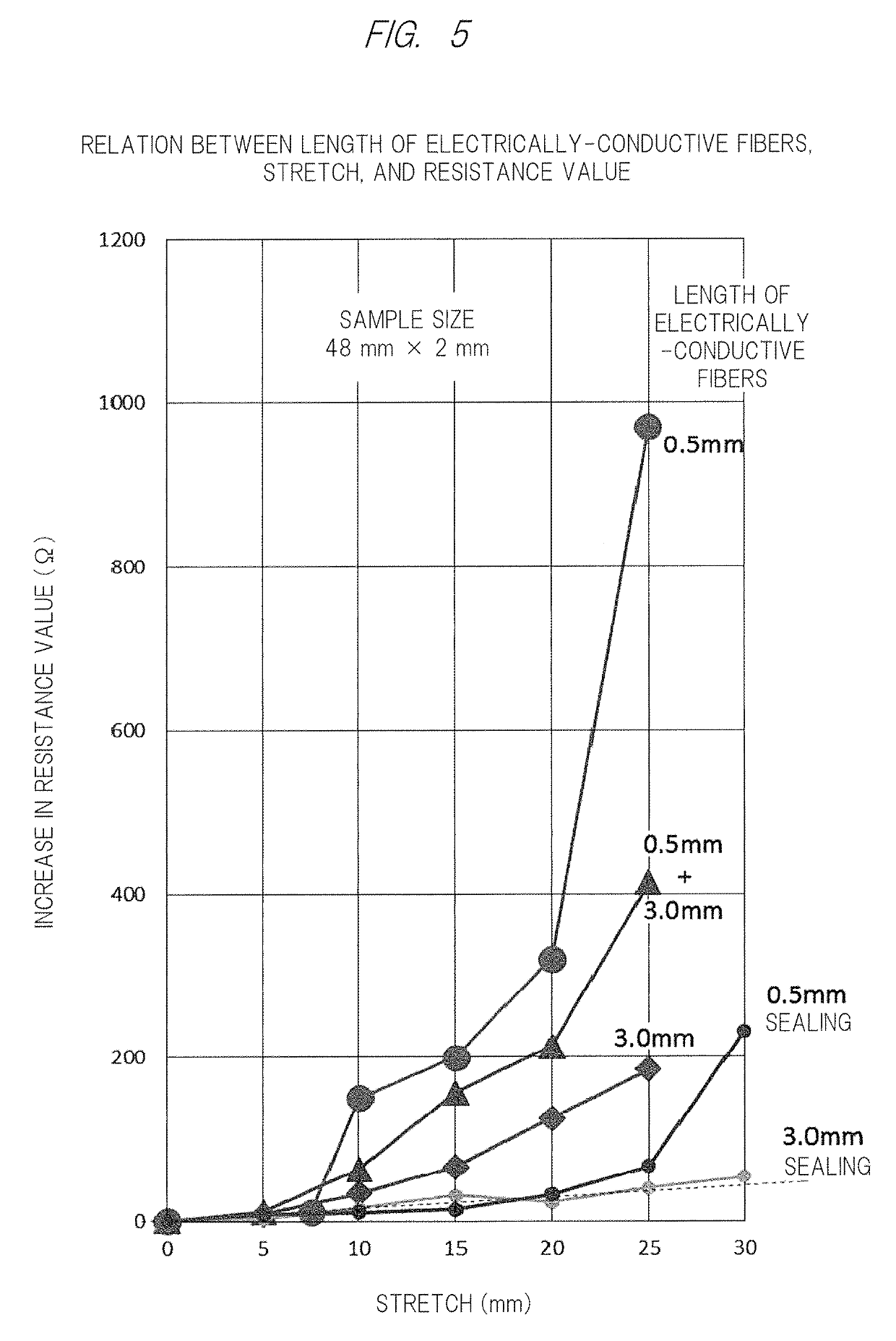
[0082]An adhesive layer was applied to the whole surface of an elastomer sheet (for example, a urethane elastomer sheet having a size of 3 cm×8 cm and a thickness of 1 mm) having predetermined flexibility. With viscosity appearing on the adhesive layer to some extent, silver-plated nylon fibers each having a length of 0.5 mm to 3 mm and a diameter of 17.6 μm were attached to the adhesive layer as the electrically-conductive fiber materials by the brush roller method. Sheet resistance of the stretchable electrically-conductive sheet was measured by a resistance meter. Actual measured results are indicated in FIG. 6.

[0083]There was a small change in sheet resistance up to a 250% stretch rate, which indicated a preferable characteristic.

example 2

[0084]Silver-plated nylon fibers (a fiber length of 0.3 mm to 3 mm, a fiber diameter of 17.6 μm) were adsorbed to an adhesive layer of an elastomer adhesive sheet (a size of 3 cm×8 cm, a thickness of 1 mm) by the brush roller spray method. The electrically-conductive sheet was brought into contact with an LED lighting circuit wire, and luminance of the LED was visually observed when a stretch rate was approximately 100%. Comparing to a case when the stretch rate was 0%, change in luminance was not observed.

example 3

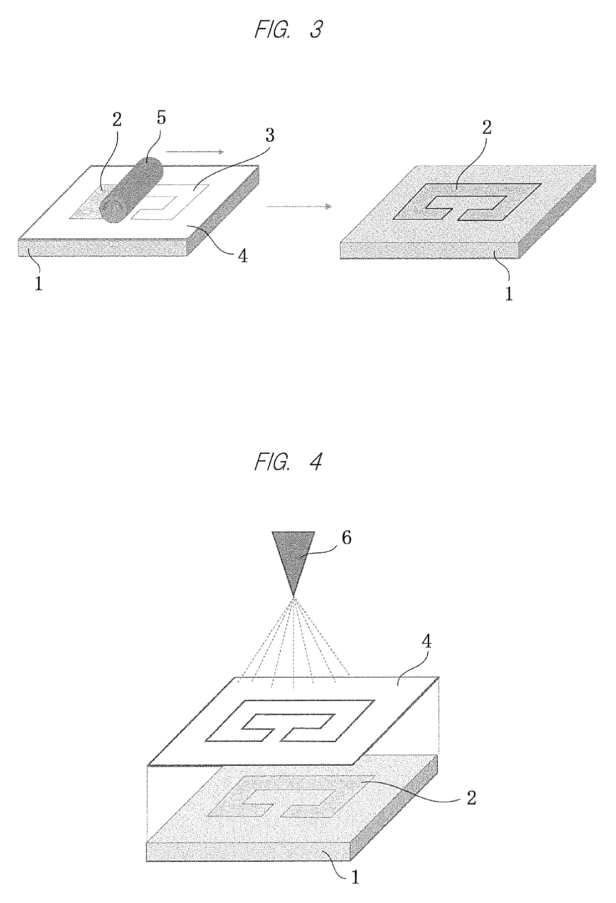
[0085]An antenna pattern for UHF-RFID was formed by forming a mask in which PET was cut on an adhesive layer of an elastomer adhesive sheet (a size of 3 cm×9 cm, a thickness of 1 mm) and by adsorbing silver-plated nylon fibers (a fiber length of 0.3 mm to 3 mm, a fiber diameter of 17.6 μm) to the mask by the brush roller method. The antenna pattern was mounted with an IC chip for RFID conforming to EPC global gen2 to form a stretchable RFID tag. Attaching the stretchable RFID tag to clothing, a readout experiment was carried out by an RFID readout device (BHT-604QUWB made by DENSO WAVE Inc., at an output of 10 mW).

[0086]The ID could be read out within a communication distance of approximately 3 cm. Even when a stretch rate reached approximately 100%, the communication distance could be maintained within approximately 2.5 cm.

[0087]Note that, in Examples 1 to 3, there were no big differences among the experimental results even in a case of sticking the silver-plated nylon fibers by th...


PUM

PropertyMeasurementUnit
thicknessaaaaaaaaaa
sizeaaaaaaaaaa
diameteraaaaaaaaaa

Abstract

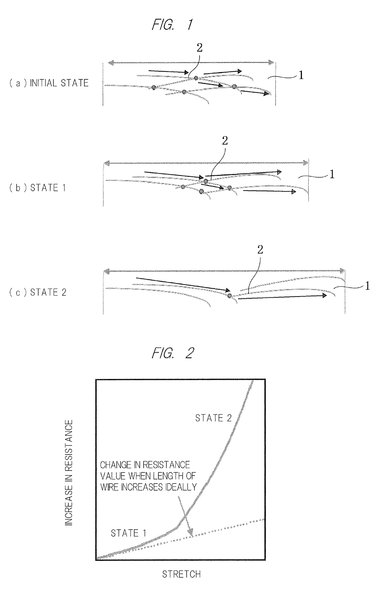
A stretchable electrically-conductive sheet according to the present invention includes an elastomer sheet 1 having an adhesive layer corresponding to a wiring region with a predetermined pattern formed on a front surface of the elastomer sheet, and also includes electrically-conductive fiber materials 2 each having a predetermined diameter and a predetermined length. When the elastomer sheet 1 is stretched or bended, the electrically-conductive fiber materials relatively move maintaining mutual electrical continuity so as to maintain the electrical continuity in the wiring region. Accordingly, it is possible to achieve a low-cost stretchable electrically-conductive circuit having excellent stretchability, bendability, and durability.

Description

CROSS-REFERENCE TO RELATED APPLICATIONS[0001]This application is a National Stage application of International Patent Application No. PCT / JP2015 / 063943, filed on May 14, 2015, which claims priority to Japanese Patent Application Numbers 2014-102087, filed on May 16, 2014 and 2014-252330, filed on Dec. 12, 2014, each of which is hereby incorporated by reference in its entirety.TECHNICAL FIELD[0002]The present invention relates to a stretchable electrically-conductive circuit having excellent stretchability and bendability and a method for manufacturing the same.BACKGROUND ART[0003]Recently, demand for such a stretchable electrically-conductive circuit has been increased in various fields, for example, an antenna or a wire for RFID devices requiring flexibility, a wire for a motion analysis sensor in sports science, a wearable heartbeat / electrocardiogram monitor, a wire in a robot movable portion, and a wire for a finger sensor in order to transmit commands to a computer. Furthermore,...

Claims


Application Information

Patent Timeline
Patent Type & Authority Patents(United States)
IPC IPC(8): G01L1/00G01L1/14B32B25/10H05K3/10H05K3/14H05K1/02H01R11/01H01B13/00H01B7/06H01B5/00H01B5/02H01B5/14H01G5/18H05K1/03
CPCG01L1/144H01B5/00H01B5/02H01B5/14H01B7/06H01B13/00H01R11/01H05K1/0283H05K3/103H05K3/143B32B25/10H05K2201/0314H01G5/18H05K1/0393H05K2201/0133H05K1/02H05K1/03H05K1/09H05K3/10
Inventor YOSHIDA, MANABUUEMURA, SEINOBESHIMA, TAIKI
Owner NAT INST OF ADVANCED IND SCI & TECH
Learn More