
Timing based LNA gain adjustment in an RF receiver to compensate for intermodulation interference

a receiver and intermodulation interference technology, applied in the field of wireless communication, can solve the problems of reducing the snr of the signal produced by the mixer, reducing the gain of the lna, and not working the technique of setting the lna gain

Inactive Publication Date: 2005-03-29
AVAGO TECH WIRELESS IP SINGAPORE PTE
View PDF10 Cites 42 Cited by
  • Summary
  • Abstract
  • Description
  • Claims
  • Application Information

AI Technical Summary

Benefits of technology

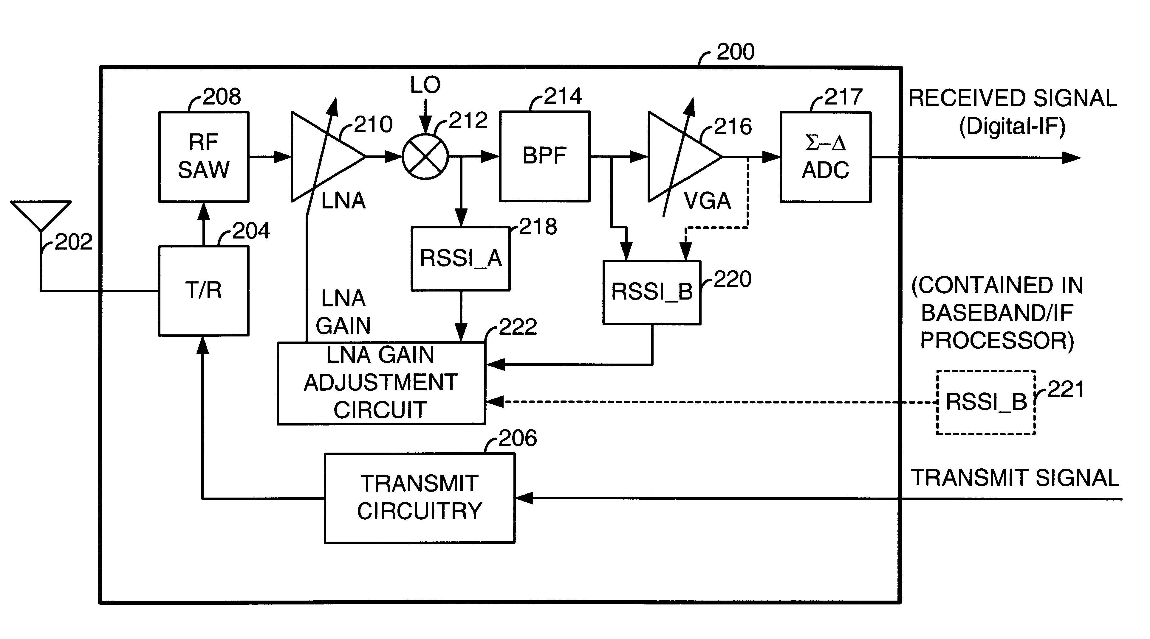
According to the present invention, this RF receiver includes a wideband received signal strength indicator (RSSI_A) coupled to the output of the mixer that measures the strength of the wideband signal at that point. A second received signal strength indicator (RSSI_B) couples to the received signal path after the BPF and measures the strength of the narrowband signal of interest after the BPF. Thus, in combination, the RSSI_A and the RSSI_B indicate the respective strengths of the wideband signal produced by the mixer and the narrowband signal produced by the mixer after filtering by the BPF, respectively. The structure of the present invention also includes an LNA gain adjustment block that receives the RSSI_A and RSSI_B indications, and controls the gain of the LNA to maintain linearity of the mixer and also to maximize the Signal to Noise Ratio (SNR) of the IF signal of interest produced by the RF receiver.

Problems solved by technology

However, when intermodulation interference exists, this technique for setting the LNA gain does not work.
Intermodulation interference in the mixer occurs when the mixer receives two or more strong RF interference signals at certain neighboring channels (in addition to the desired signal) that cause the mixer to produce intermodulation components at the IF, the same frequency as the desired signal.
However, reducing the gain of the LNA also reduces the SNR of the signal produced by the mixer.
While this problem is well known, its solution is not.
However, it did not consider whether intermodulation interference existed.
Additional difficulties arise when the receiver operates in a Time Division Multiple Access (TDMA) system in which transmissions from differing locations are non-time-aligned.
However, in TDMA systems, data frames of differing base stations are typically not time aligned.
When the interfering signals become active during the time slot, an IM3 component is produced in the mixer, causing the receiver to fail to correctly receive the data contained in the time slot.

Method used


Image

  • Timing based LNA gain adjustment in an RF receiver to compensate for intermodulation interference
  • Timing based LNA gain adjustment in an RF receiver to compensate for intermodulation interference
  • Timing based LNA gain adjustment in an RF receiver to compensate for intermodulation interference

Examples


Embodiment Construction

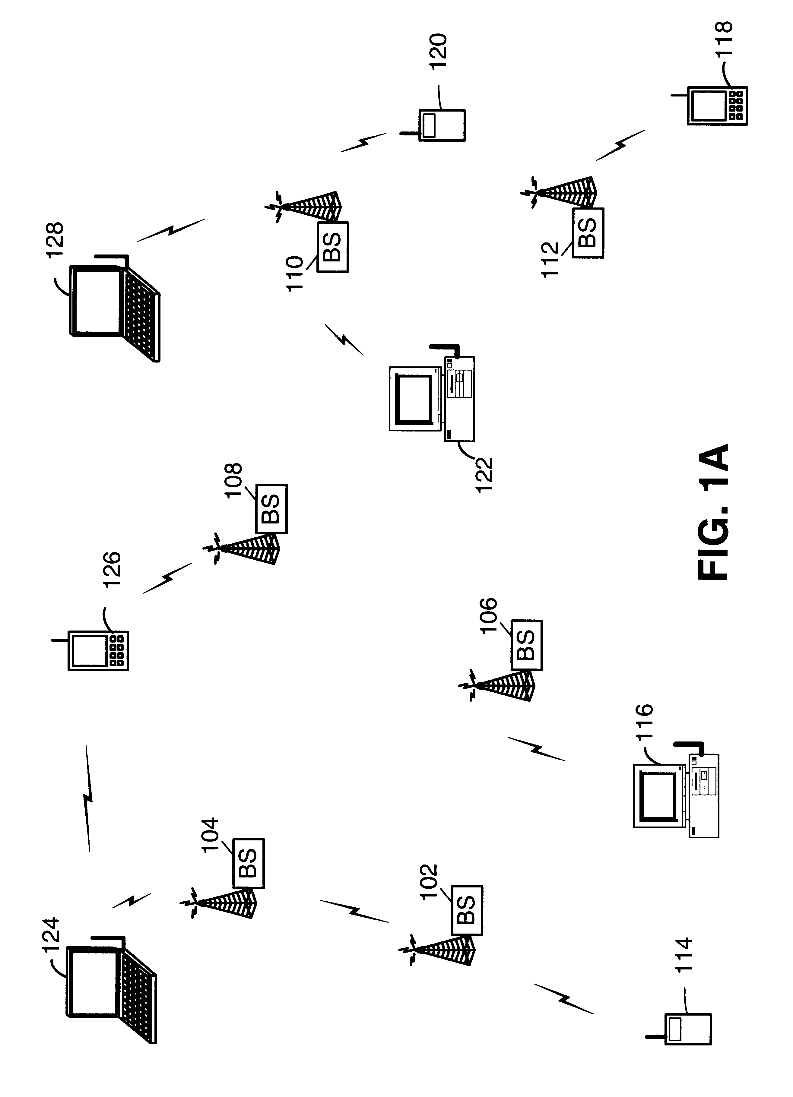
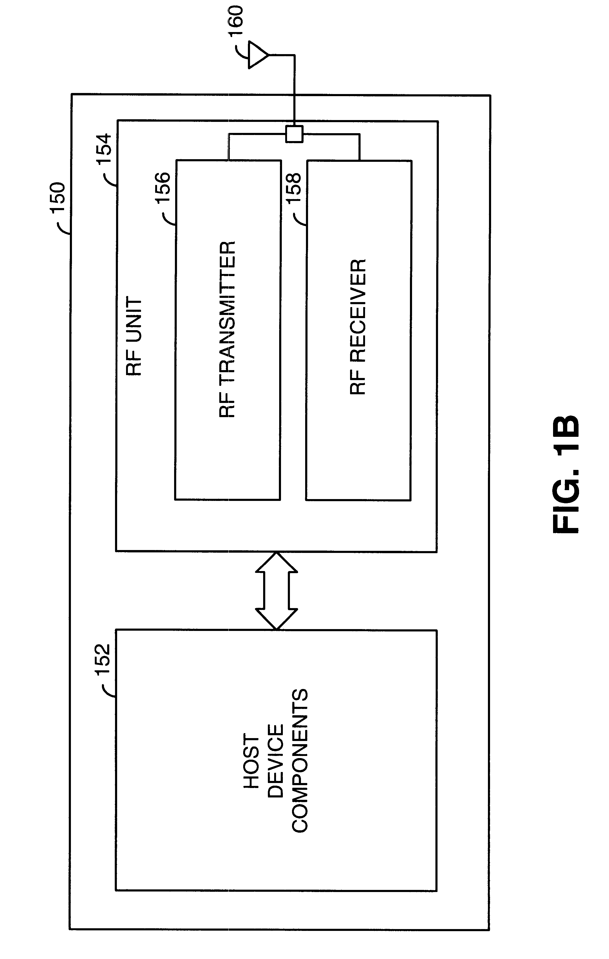
FIG. 1A is a system diagram illustrating a cellular system within which the present invention is deployed. The cellular system includes a plurality of base stations 102, 104, 106, 108, 110, and 112 that service wireless communications within respective cells / sectors. The cellular system services wireless communications for a plurality of wireless subscriber units. These wireless subscriber units include wireless handsets 114, 120, 118, and 126, mobile computers 124 and 128, and desktop computers 116 and 122. When wirelessly communicating, each of these subscriber units communicates with one (or more during handoff) of the base stations 102 through 112. Each of the subscriber units of FIG. 1A, both subscriber units and base stations includes a radio frequency (RF) unit.

The services provided by the cellular system include both voice service and data services. Such services are provided according to a cellular networking standard such as the GSM standard, the IS-136 standard, the 1XEV-...


PUM


Abstract

A Radio Frequency (RF) receiver includes a low noise amplifier (LNA) and a mixer coupled to the output of the LNA. The gain of the LNA is adjusted to maximize signal-to-noise ratio of the mixer and to force the mixer to operate well within its linear region when an intermodulation interference component is present. The RF receiver includes a first received signal strength indicator (RSSI_A) coupled to the output of the mixer that measures the strength of the wideband signal at that point. A second received signal strength indicator (RSSI_B) couples after the BPF and measures the strength of the narrowband signal. The LNA gain is set based upon these signal strengths. LNA gain is determined during a guard period preceding an intended time slot of a current frame and during a guard period following an intended time slot of a prior frame. The lesser of these two LNA gains is used for the intended time slot of the current frame.

Description

1. FIELD OF THE INVENTIONThis invention relates generally to wireless communications; and more particularly to the operation of a Radio Frequency (RF) receiver within a component of a wireless communication system.2. BACKGROUND OF THE INVENTIONThe structure and operation of wireless communication systems is generally known. Examples of such wireless communication systems include cellular systems and wireless local area networks, among others. Equipment that is deployed in these communication systems is typically built to support standardized operations, i.e. operating standards. These operating standards prescribe particular carrier frequencies, modulation types, baud rates, physical layer frame structures, MAC layer operations, link layer operations, etc. By complying with to these operating standards, equipment interoperability is achieved.In a cellular system, a governmental body licenses a frequency spectrum for a corresponding geographic area (service area) that is used by a li...

Claims


Application Information

Patent Timeline
Patent Type & Authority Patents(United States)
IPC IPC(8): H03G3/20H03G3/30H03F1/32H04B1/10
CPCH03F1/32H04B1/109H03G3/3068H03G3/3078H03G3/3052H03F2200/294H03F2200/372
Inventor SHI, HONG
Owner AVAGO TECH WIRELESS IP SINGAPORE PTE
Learn More