
Spread Spectrum Device and Related Random Clock Generator for a Switching Amplifier

a technology of random clock generator and spectrum device, which is applied in the direction of pulse characteristics measurement, pulse technique, instruments, etc., can solve the problems of low linearity of triangular wave generated in the prior art, high cost and space, and dramatic discount of switching amplifier advantages, etc., to achieve low cost, low electromagnetic interference, and low output signal distortion

Active Publication Date: 2008-12-11
ANPEC ELECTRONICS CORPORATION
View PDF4 Cites 12 Cited by
  • Summary
  • Abstract
  • Description
  • Claims
  • Application Information

AI Technical Summary

Benefits of technology

[0007]It is therefore a primary objective of the claimed invention to provide a switching amplifier with output signal feedback correction to lower output signal distortion dramatically and use a spread spectrum device with feedback control to maintain the linearity of the triangular wave for achieving the purpose of low cost, Hi-Fi, and low electromagnetic interference.

Problems solved by technology

But advantages of switching amplifiers are dramatically discounted because of the increased cost and space of low pass filters.
But linearity of the triangular wave generated in the prior art is not good and easily causes serious distortion problems.

Method used


Image

  • Spread Spectrum Device and Related Random Clock Generator for a Switching Amplifier
  • Spread Spectrum Device and Related Random Clock Generator for a Switching Amplifier
  • Spread Spectrum Device and Related Random Clock Generator for a Switching Amplifier

Examples


Embodiment Construction

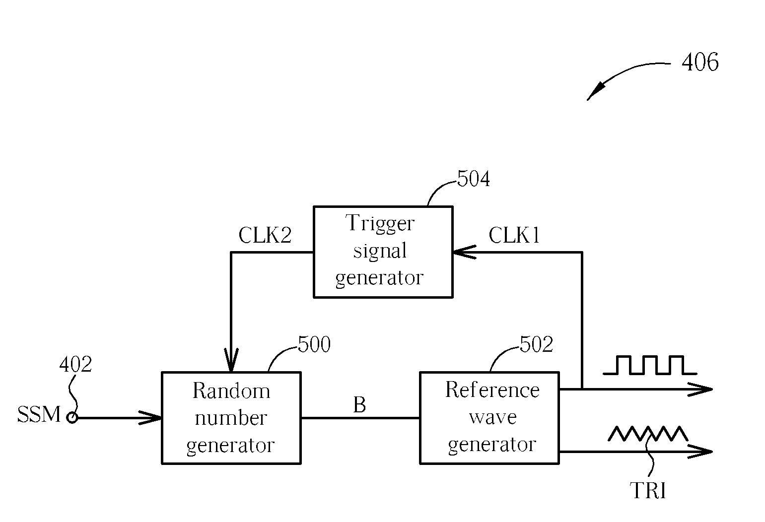
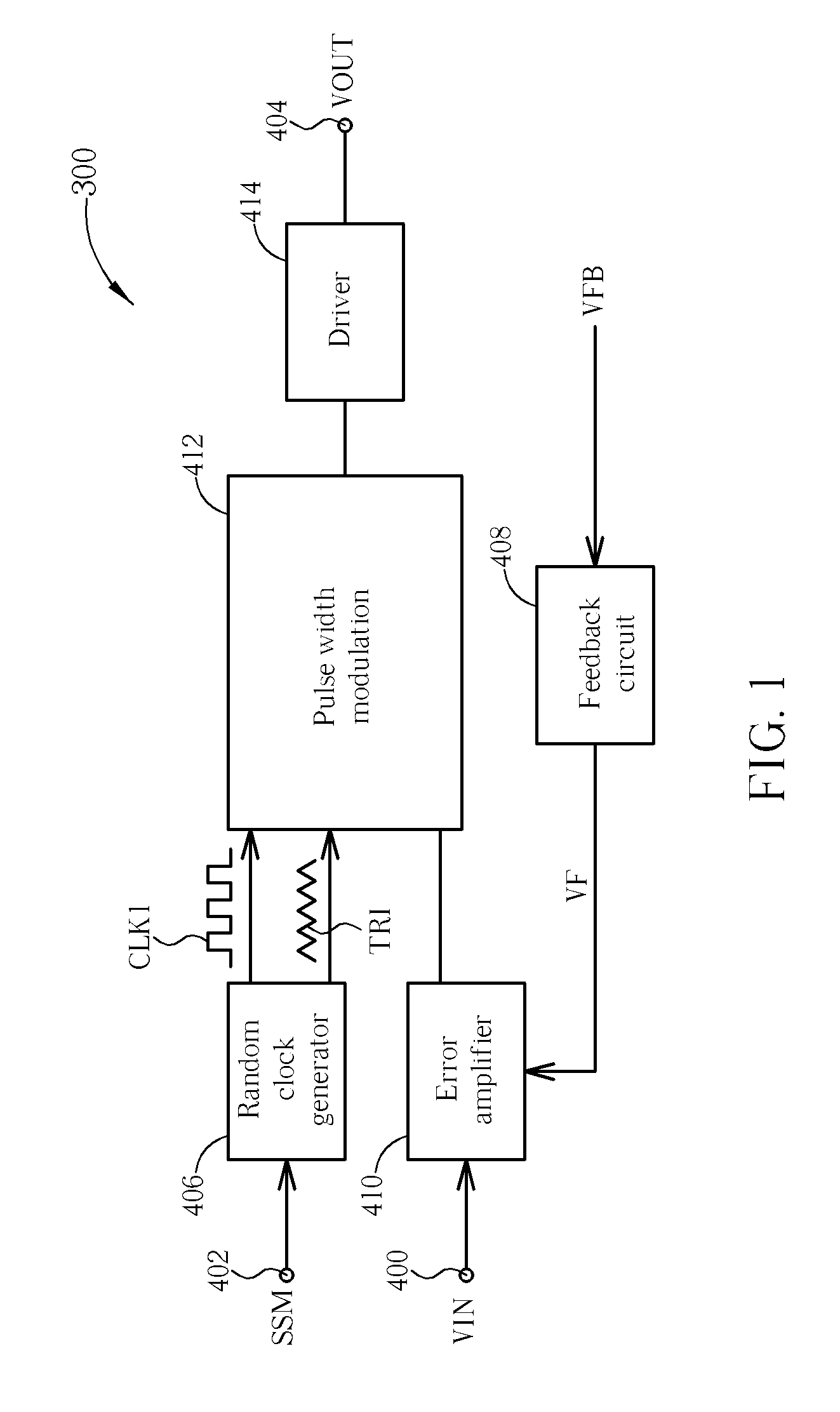
[0021]Please refer to FIG. 1. FIG. 1 illustrates a schematic diagram of a switching amplifier 300 of a spread spectrum pulse width modulation unit according to an embodiment of the present invention. The switching amplifier 300 of a spread spectrum pulse width modulation unit comprises an input end 400, a controlling end 402, an output end 404, a random clock generator 406, a feedback circuit 408, an error amplifier 410, a pulse width modulation unit 412, and a driver 414. The input end 400 is utilized for receiving the source VIN generated by an audio generation unit (not shown in FIG. 1). Through the pulse width modulation unit 412, the output end 404 outputs a driving signal VOUT to a speaker (not shown in FIG. 1). The random clock generator 406 coupled to the controlling end 402 is utilized for generating a triangular wave signal TRI and a square wave signal CLk1 with fixed frequency or spread spectrum according to a control signal received by the controlling end 402. The feedba...


PUM


Abstract

A random clock generator for a spread spectrum modulating device includes a random number generator for generating a plurality of random number signals according to a first square wave signal and a control signal, a reference wave generator coupled to the random number generator for generating a triangular signal and a second square wave signal according to the plurality of random number signals, and a trigger signal generator coupled to the random number generator and the reference wave generator, for generating the first square wave signal according to the second square wave signal.

Description

CROSS REFERENCE TO RELATED APPLICATIONS[0001]This application claims the benefit of U.S. Provisional Application No. 60 / 942,211, filed on Jun. 6, 2007 and entitled “Spread spectrum modulation for switching amplifier and switching regulator”, the contents of which are incorporated herein by reference.BACKGROUND OF THE INVENTION[0002]1. Field of the Invention[0003]The present invention is related to a spread spectrum device and related random clock generator for a switching amplifier, and more particularly, to a spread spectrum device and related random clock generator capable of lowering electromagnetic interference of output signals of the switching amplifier.[0004]2. Description of the Prior Art[0005]Because a switching amplifier has a high operational efficiency approaching ninety percent, the switching amplifier becomes a primary choice of mobile devices with low power cost. Compared to traditional AB type of amplifiers at the same output wattage, the switching amplifiers have lo...

Claims


Application Information

Patent Timeline
Patent Type & Authority Applications(United States)
IPC IPC(8): H03K3/84
CPCH03F3/2175H03K3/84H03K7/08
Inventor CHANG, MING-HUNG
Owner ANPEC ELECTRONICS CORPORATION
Learn More