
Clock processing logic and method for determining clock signal characteristics in reference voltage and temperature varying environments

a clock signal and clock processing logic technology, applied in the field can solve the problems of destroying the limited timing budget available for read data capture, affecting the accuracy of clock signal processing, etc., to achieve cost-effective and simple implementation

Inactive Publication Date: 2005-03-15
SK HYNIX INC
View PDF3 Cites 10 Cited by
  • Summary
  • Abstract
  • Description
  • Claims
  • Application Information

AI Technical Summary

Benefits of technology

The present invention provides a clock processing logic and method that can determine clock signal characteristics in reference voltage and temperature varying environments. It can generate a compensated percent-of-clock period delayed signal that compensates for reference voltage and temperature variations. The logic is cost-effective and simple to implement. It can also detect edges of a clock signal in a noisy environment and measure the period of a clock signal and jitter. The technical effects of the invention include improved accuracy and reliability in clock signal processing, regardless of environmental variations.

Problems solved by technology

Read data capture at the memory controller, however, can be a significant challenge using DDR SDRAMs.
Each of these implementations, however, is susceptible to process, voltage and temperature variations that may significantly alter the value of their delay line.
Such variations may destroy the limited timing budget available for read data capture.
However, multiple clock periods are generally required for the DLL to “lock” in these implementations, thereby objectionably adding to the effective read access time in short burst read data captures.

Method used


Image

  • Clock processing logic and method for determining clock signal characteristics in reference voltage and temperature varying environments
  • Clock processing logic and method for determining clock signal characteristics in reference voltage and temperature varying environments
  • Clock processing logic and method for determining clock signal characteristics in reference voltage and temperature varying environments

Examples


Embodiment Construction

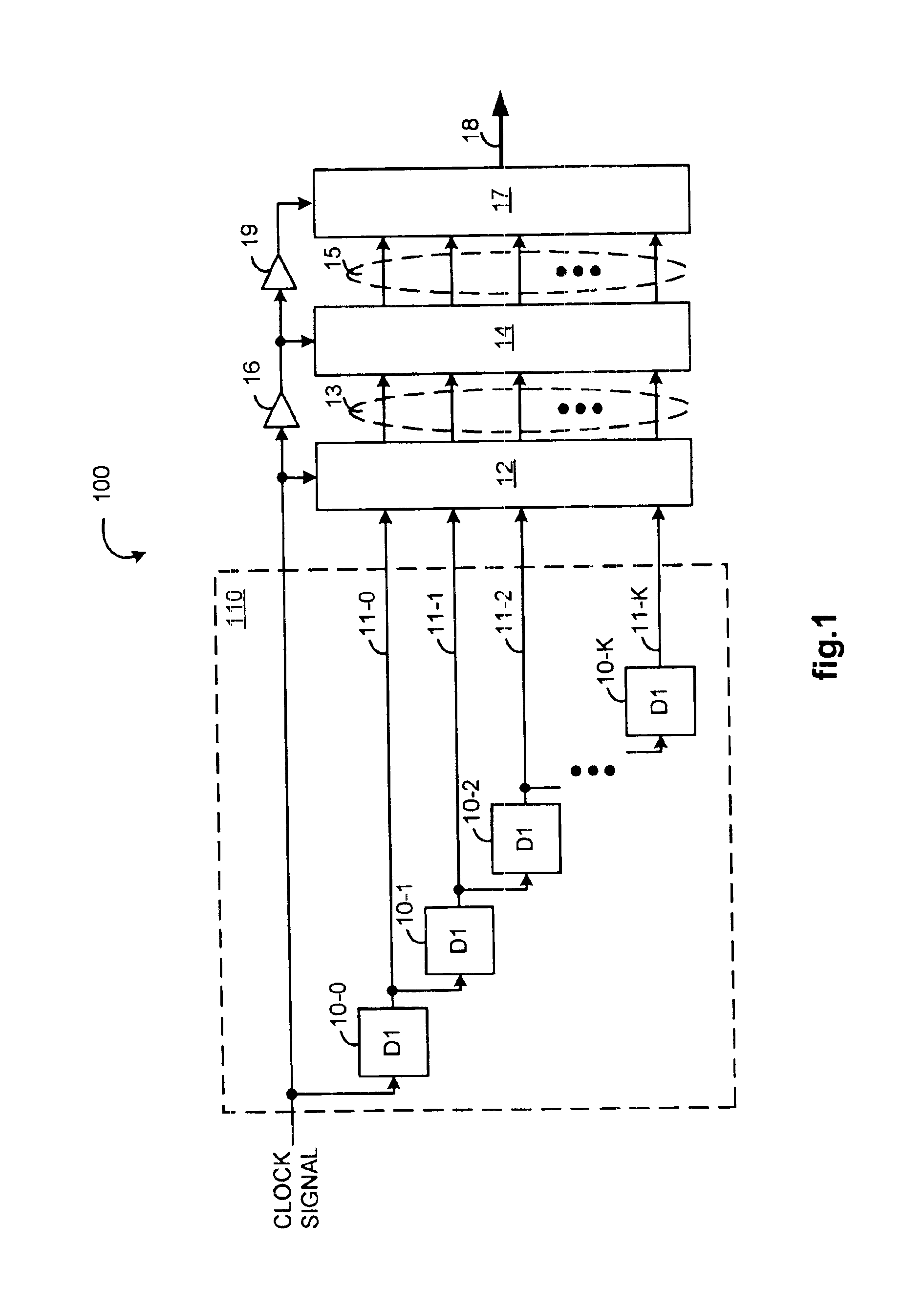
FIG. 1 illustrates, as an example, a first circuit 100 as part of an apparatus for generating a compensated percent-of-clock period delayed signal. A first delay tree 110 has (K+1) delay branches 11-0 to 11-K that are sequentially configured so as to have increasing numbers of serially coupled first delay elements individually of substantially a first delay value D1, so that each of the branches provides incrementally more delay than a previous branch in sequence. In particular, in the first delay tree 110, a first delay branch 11-0 includes a single delay element 10-0, a second delay branch 11-1 includes two delay elements 10-0 and 10-1, a third delay branch 11-2 includes three delay elements 10-0, 10-1, and 10-2, and so on, down to a (K+1)th delay branch 11-K that includes K+1 delay elements 10-0 to 10-K.

A clock signal is provided to each of the delay branches 11-0 to 11-K through their common delay element 10-0, to an enable input of a first register 12, and to a buffer 16. Outpu...


PUM


Abstract

Clock processing logic and method for determining clock signal characteristics in reference voltage and temperature varying environments are described. A sample vector is characterized by bit locations corresponding to sequentially increasing delay values so that values stored in such bit locations indicate clock signal edges where value transitions occur. In one embodiment, edge detection logic and sensitivity adjustment logic are used in determining the clock period from such a sample vector. In another embodiment, an edge filter, sample accumulation logic, and clock period and jitter processing logic are used in determining an average clock period and clock jitter from a predefined number of such sample vectors.

Description

FIELD OF THE INVENTIONThe present invention generally relates to clock signal processing and in particular, to a clock processing logic and method for determining clock signal characteristics in reference voltage and temperature varying environments.BACKGROUND OF THE INVENTIONClock processing logic and method for determining clock signal characteristics in reference voltage and temperature varying environments are useful in many applications including those for generating a compensated percent-of-clock period delay signal. The generation of compensated percent-of-clock period delay signals is, in turn, also useful in many applications. As an example, such a delayed version of a data strobe signal (DQS) is useful for capturing read data (DQ) provided along and edge-aligned with the DQS from a double data rate (DDR) synchronous dynamic random access memory (SDRAM).The benefits of DDR SDRAMs are well known. Simply put, DDR SDRAMs are probably the most straightforward and least costly a...

Claims


Application Information

Patent Timeline
Patent Type & Authority Patents(United States)
IPC IPC(8): H03K5/13H03K5/06H03K5/135H03K5/04G11C7/22
CPCG11C7/22G11C7/222H03K5/133H03K5/135H03K5/06G11C7/04
Inventor TALLEDO, CESAR A.STEINBERG, DANIEL R.
Owner SK HYNIX INC
Learn More