Hybrid intravascular stent

Inactive Publication Date: 2005-03-15
ABBOTT CARDIOVASCULAR
View PDF17 Cites 279 Cited by
  • Summary
  • Abstract
  • Description
  • Claims
  • Application Information

AI Technical Summary

Benefits of technology

In another embodiment of the present invention, a method of making a hybrid stent having alternating rings and links formed of a biocompatible polymer material for use in a body lumen is disclosed. This hybrid approach creates a stent that exhibits the desirable characteristics of high flexibility and high radial strength. The flexibility of the stainless steel stent is increased by incorporating the mechanical advantages of polymers (i.e., lower stress, higher strain) to form alternating rings of polymers and connector links along the length of the stent for a more flexible stent system.
In yet another embodiment of the present invention, a linkless hybrid stent is fabricated with alternating cylindrical rings of a polymer material in which adjacent cylindrical rings are directly attached to each other at the peaks, such as by welding. The alternating polymer cylindrical rings can be selectively placed at the stent ends to prevent vessel wall injury at the edges of the stent.
In a further embodiment of the present invention, a laminated, linkless polymer stent is fabricated by laminating a plurality of cylindrical stent rings between two polymer tubes. The lamination of the rings can be performed in accordance with techniques known in the art, such as laser bonding and blow molding. The presence of the polymer tube provides support to an increased portion of the arterial wall thereby increasing the stent scaffolding. The radiopacity of the stent can be increased using metals such as gold, paladium, platinum, and iradium. Further, the stent can be made MRI-compatible by using gold or silver in place of stainless steel.
One preferred structure for the expandable cylindrical rings which form the stent of the present invention is generally a circumferential undulating pattern, e.g., serpentine. The open reticulated structure of the stent allows for the perfusion of blood over a large portion of the arterial wall which can improve the healing and repair of a damaged arterial lining.
When the stent is expanded, the radial expansion of the expandable cylindrical rings deforms the undulating or serpentine pattern similar to changes in a waveform which result from decreasing the waveform's amplitude and the frequency. The undulating patterns of the individual cylindrical rings can be in phase with each other or out of phase, depending on the stent design. The cylindrical rings of the stent are plastically deformed when expanded so that the stent will remain in the expanded condition and therefore they must be sufficiently rigid when expanded to prevent the collapse thereof in use. During expansion of the stent, portions of the undulating pattern tip outwardly resulting in projecting members on the outer surface of the expanded stent. These projecting members tip radially outwardly from the outer surface of the stent and embed into the vessel wall and help secure the expanded stent so that it does not move once it is implanted.
The number and location of links connecting the rings can be varied in order to vary the desired longitudinal and flexural flexibility in the stent structure both in the unexpanded as well as the expanded condition. These properties are important to minimize alteration of the natural physiology of the body lumen into which the stent is implanted and to maintain the compliance of the body lumen which is internally supported by the stent. Generally, the greater the longitudinal and flexural flexibility of the stent, the easier and the more safely it can be delivered to the target site.

Problems solved by technology

One of the difficulties encountered using prior stents involved maintaining the radial rigidity needed to hold open a body lumen while at the same time maintaining the longitudinal flexibility of the stent to facilitate its delivery.
While other numerous prior art stents have had sufficient radial strength to hold open and maintain the patency of a coronary artery, they have lacked the flexibility required to easily navigate tortuous vessels without damaging the vessels during delivery.
A disadvantage may be that the metallic stent lacks flexibility which is important during the delivery of the stent to the target site.
With respect to polymer stents, they may have a tendency to be quite flexible and are advantageous for use during delivery through tortuous vessels, however, such polymer stents may lack the radial strength necessary to adequately support the lumen once implanted.

Method used


Image

  • Hybrid intravascular stent
  • Hybrid intravascular stent
  • Hybrid intravascular stent

Examples


Embodiment Construction

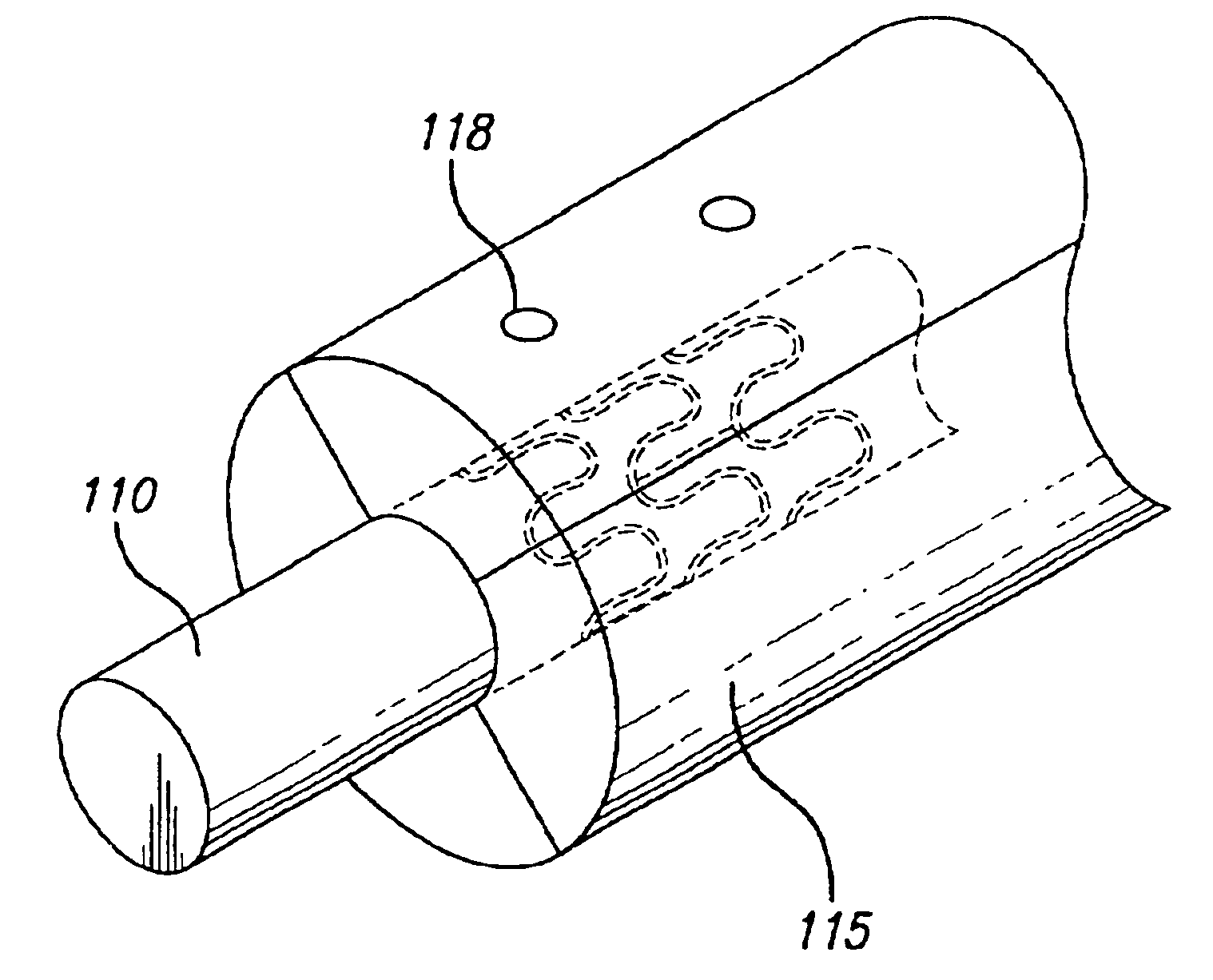
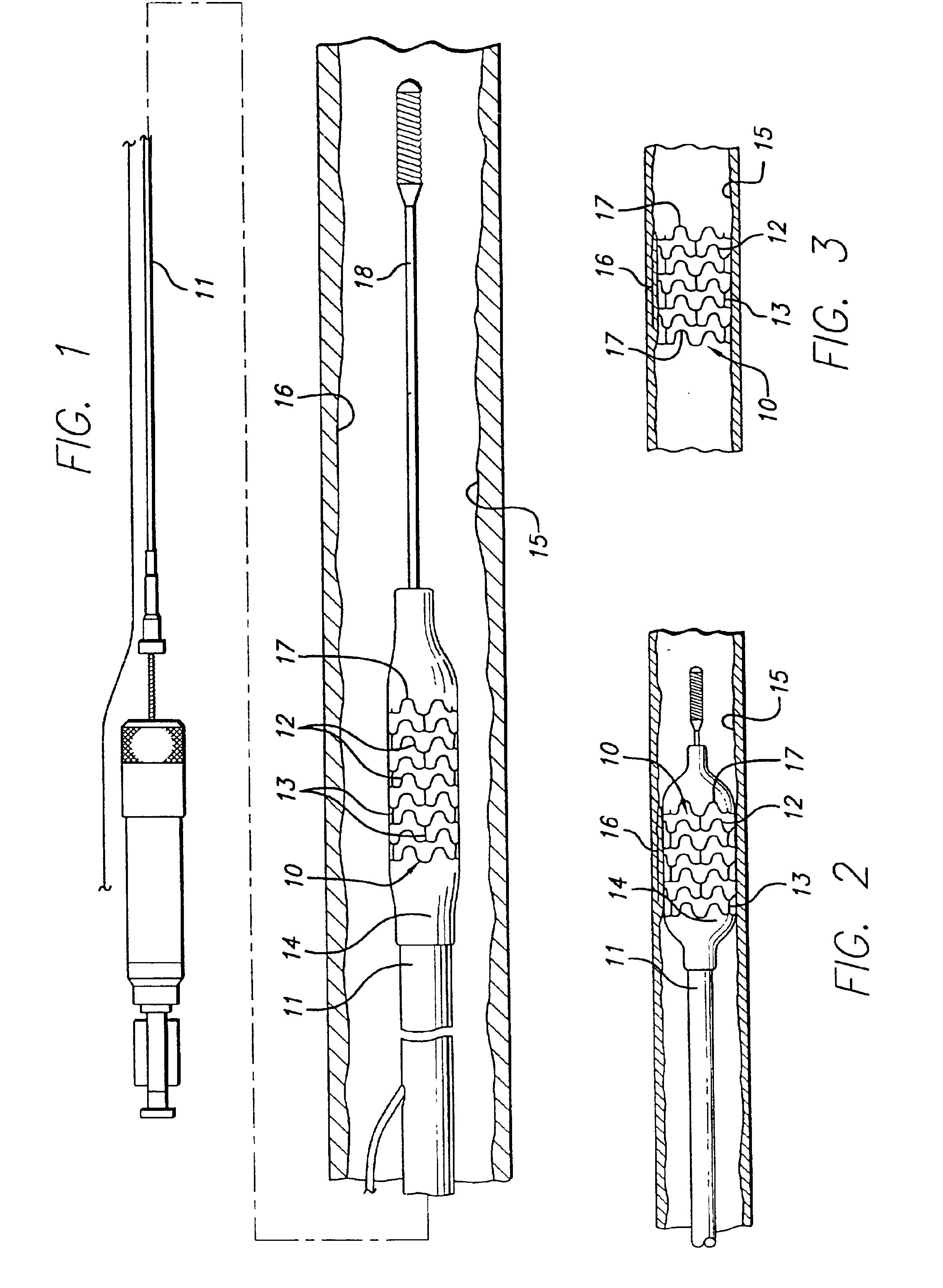
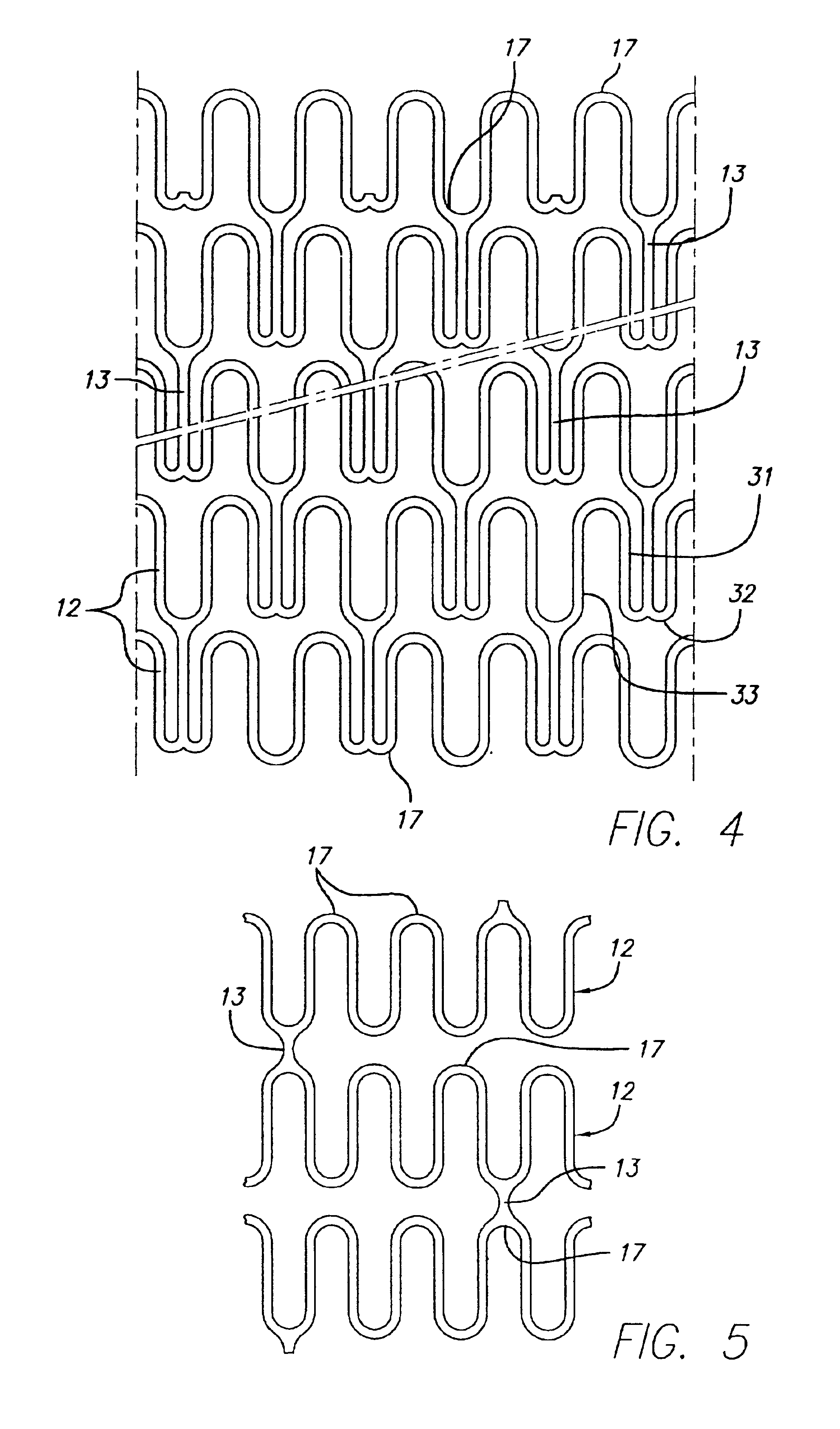
FIG. 1 illustrates a stent 10 incorporating features of the invention which is mounted onto a delivery catheter 11. The stent generally comprises a plurality of radially expandable cylindrical rings 12 disposed generally coaxially and interconnected by links 13 disposed between adjacent cylindrical elements. The delivery catheter 11 has an expandable portion or balloon 14 for expansion of the stent 10 within an artery 15. The artery 15, as shown in FIG. 1, has an occluded portion of the arterial passageway that has been opened by a previous procedure, such as angioplasty.

The delivery catheter 11 onto which the stent 10 is mounted, is essentially the same as a conventional balloon dilatation catheter for angioplasty procedures. The balloon 14 may be formed of suitable materials such as polyethylene, polyethylene terephthalate, polyvinyl chloride, nylon and ionomers such as Surlyn® manufactured by the Polymer Products Division of the Du Pont Company. Other polymers may also be used. I...


PUM

PropertyMeasurementUnit
Thicknessaaaaaaaaaa
Thicknessaaaaaaaaaa
Thicknessaaaaaaaaaa

Abstract

A hybrid stent is formed which exhibits both high flexibility and high radial strength. The expandable hybrid stent for implantation in a body lumen, such as a coronary artery, consists of radially expandable cylindrical rings generally aligned on a common longitudinal axis and interconnected by one or more links. In one embodiment, a dip-coated covered stent is formed by encapsulating cylindrical rings within a polymer material. In other embodiments, at least some of the rings and links are formed of a polymer material which provides longitudinal and flexural flexibility to the stent. These polymer rings and links are alternated with metallic rings and links in various configurations to attain sufficient column strength along with the requisite flexibility in holding open the target site within the body lumen. Alternatively, a laminated, linkless hybrid stent is formed by encapsulating cylindrical rings within a polymer tube.

Description

BACKGROUND OF THE INVENTIONThis invention relates to expandable endoprosthesis devices, generally called stents, which are adapted to be implanted into a patient's body lumen, such as a blood vessel, to maintain the patency thereof. These devices are useful in the treatment of atherosclerotic stenosis in blood vessels.Stents are generally tubular-shaped devices which function to hold open a segment of a blood vessel, coronary artery, or other anatomical lumen. They are particularly suitable for use to support and hold back a dissected arterial lining which can occlude the fluid passageway therethrough.Various means have been described to deliver and implant stents. One method frequently described for delivering a stent to a desired intraluminal location includes mounting the expandable stent on an expandable member, such as a balloon provided on the distal end of an intravascular catheter, advancing the catheter to the desired location within the patient's body lumen, inflating the ...

Claims


Application Information

Patent Timeline
IPC IPC(8): A61F2/06A61L31/10A61L31/14A61L31/16A61L31/08A61F2/07A61F2/91A61F2/915
CPCA61F2/07A61F2/91A61F2/915A61L31/10A61L31/16A61F2002/072A61F2002/91533A61F2002/91558A61F2230/0054Y10S623/901A61F2220/0058A61F2230/0013A61F2002/91575
Inventor HONG, JAMESBHAGAT, RAHULHOSSAINY, SYEDPRABHU, SANTOSHRAO, K.T. VENKATESWARASHAH, ASHOKSRIDHARAN, SRINIVASAN
Owner ABBOTT CARDIOVASCULAR
Why Eureka
Try Eureka