
Variable-length, high-speed asynchronous decoder circuit

a high-speed asynchronous and decoder technology, applied in the field of asynchronous decoder circuits, can solve the problems of high-speed circuit problems, high cost, and high cost, and achieve the effect of improving the throughput ra

Inactive Publication Date: 2005-03-08
THE TRUSTEES OF COLUMBIA UNIV IN THE CITY OF NEW YORK
View PDF2 Cites 29 Cited by
  • Summary
  • Abstract
  • Description
  • Claims
  • Application Information

AI Technical Summary

Benefits of technology

The present invention solves the foregoing problems by employing an innovative asynchronous design, which produces a decoder that is significantly

Problems solved by technology

In particular, the circuit must be very fast (since it is on the critical path between the processor and memory) and must also be very small (otherwise the savings in instruction memory will be lost to the area increase due to the decompression circuit).
To achieve a high performance using this type of design requires a very fast clock, introducing many very difficult high-speed circuit problems.
In fact, it is unlikely that a state machine of adequate complexity can be designed to run at the speeds required by the constant-input-rate approach on a silicon wafer produced by some semiconductor processes, such as a 0.8 μ CMOS process.
As multiple state transitions are combined, however, the complexity and circuit area of the decoder increase approximately exponentially with respect to the increased performance per clock cycle.
One disadvantage to this approach is that it requires a complex shifting network to remove variable length symbols from the input data stream, as well as more complex symbol detection circuitry than the constant-input-rate approach.
This complexity has a negative impact on the circuit area of the design.
Another disadvantage of the constant-output-rate approach is that the length of the critical path is dominated by the time to detect and decode the longest input symbol.
Thus, the vast majority of cycles are limited by a very infrequent worst-case path.
Furthermore, the input data buffer and shifting network must be wide enough to store and shift the longest of the input symbols, which is inefficient since the most frequently occurring input symbols will be shorter than the longest input symbol.

Method used


Image

  • Variable-length, high-speed asynchronous decoder circuit
  • Variable-length, high-speed asynchronous decoder circuit
  • Variable-length, high-speed asynchronous decoder circuit

Examples


Embodiment Construction

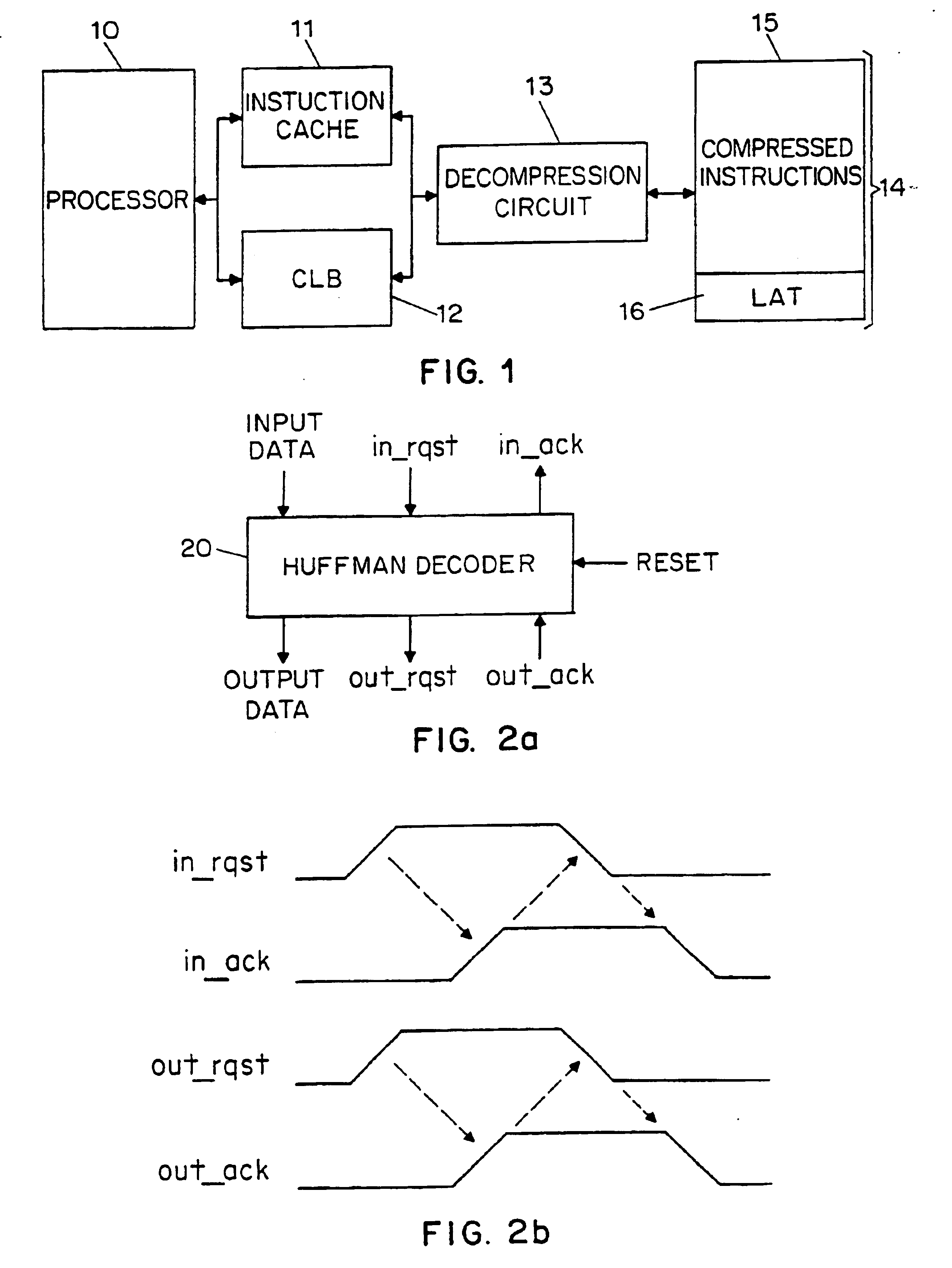
The present invention will be described in regard to a compressed-code embedded system. An embedded system is a system that incorporates microprocessors, or microcontrollers, yet is not itself a general-purpose computer. Embedded systems are now extremely widespread and are included in, for example, controllers for automobiles, airplanes, and portable consumer electronics. These systems typically include a microprocessor or microcontroller, which executes a stored program determined by the system designer. The instruction memory is either integrated on the same chip as the microprocessor or microcontroller, or is external.

Practical embedded systems are often limited by constraints on size, weight, power consumption and price. In particular, for low-cost and high-volume systems (such as portable consumer electronics systems), the cost of the system is often closely tied to the total area of the circuitry contained in the system. In such systems, a significant percentage of the area m...


PUM


Abstract

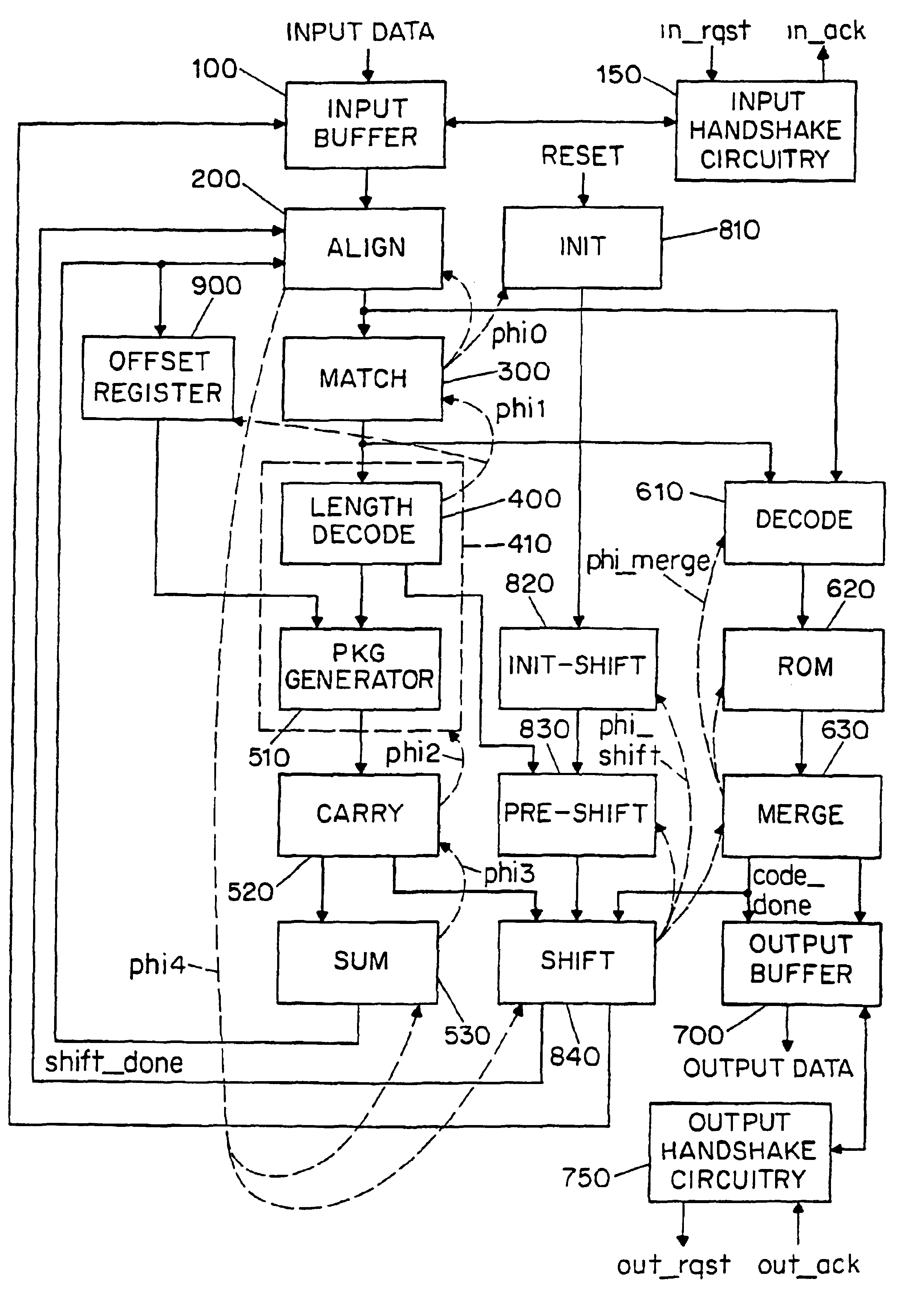
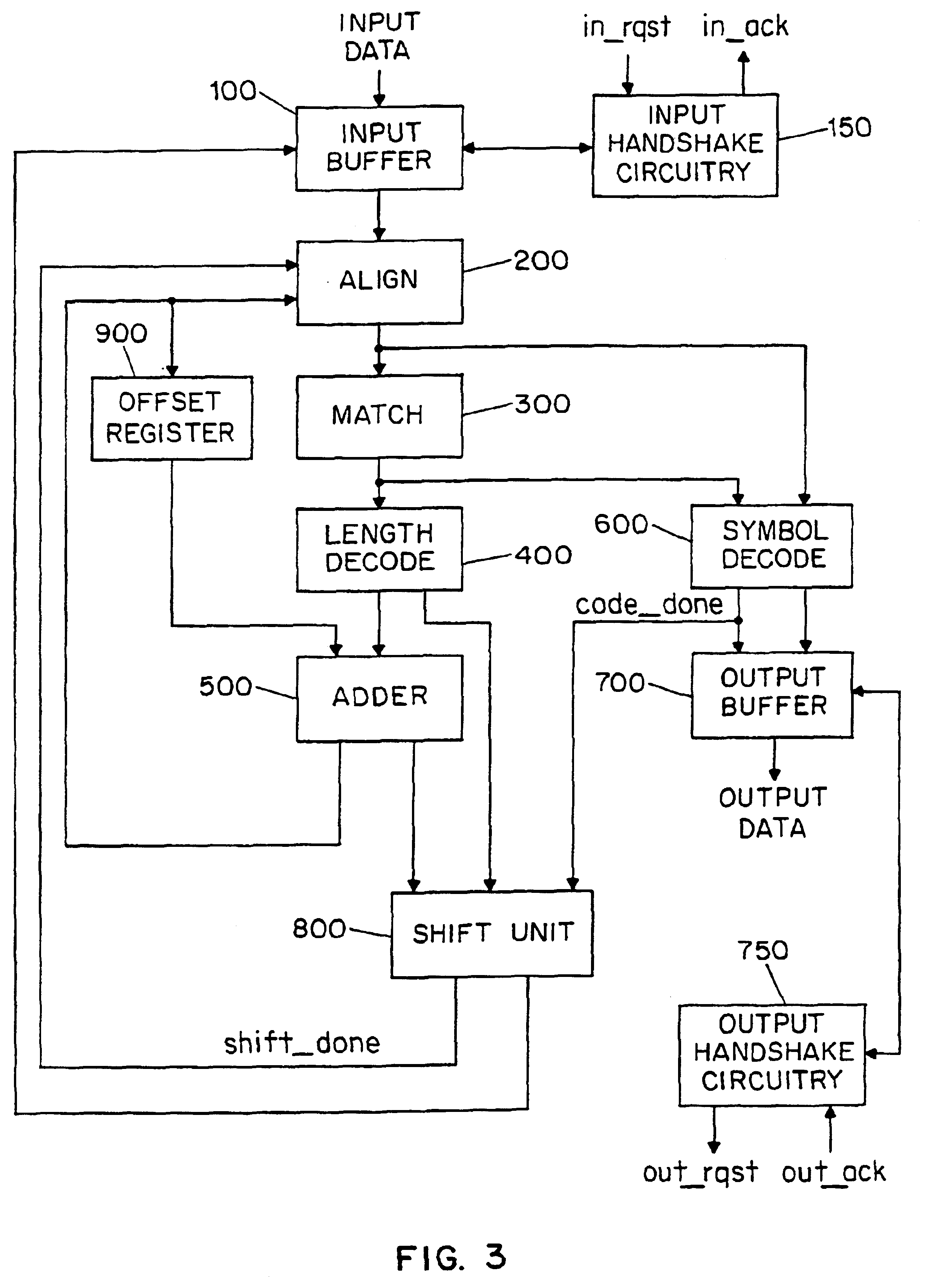
There is disclosed a decoder circuit (20) for decoding input data coded using a variable length coding technique, such as Huffman coding. The decoder circuit (20) comprises an input buffer (100), a logic circuit (150) coupled to the input buffer (100), and an output buffer (700) coupled to the logic circuit (750). The logic circuit (750) includes a plurality of computational logic stages for decoding the input data, the plurality of computational logic stages arranged in one or more computational threads. At least one of the computational threads is arranged as a self-timed ring, wherein each computational logic stage in the ring produces a completion signal indicating either completion or non-completion of the computational logic of the associated computational logic stage. Each completion signal is coupled to a previous computational logic stage in the ring. The previous computational logic stage performs control operations when the completion signal indicates completion and performs evaluation of its inputs when the completion signal indicates non-completion.

Description

BACKGROUND OF THE INVENTION1. Field of the InventionThis invention relates to an asynchronous decoder circuit. More specifically, this invention relates to an asynchronous decoder circuit that operates on data coded using a variable-length coding technique, such as Huffman coding.2. Discussion of the State of the ArtHuffman coding is a lossless coding technique that replaces fixed-length symbols with variable-length codes. Huffman codes are entropy-based, meaning that short codes are assigned to frequently occurring symbols and longer codes are assigned to less frequently occurring symbols. In addition, Huffman codes are prefix codes, meaning that each code has the property that appending additional bits to the end of the code never produces another valid code. Advantageously, Huffman coding has been used for the compression of data.In most applications utilizing Huffman-coded data, the speed and size of a Huffman decoder are important. For example, Huffman decoders may be used in c...

Claims


Application Information

Patent Timeline
IPC IPC(8): G06T9/00H04N7/26H04N7/50
CPCH04N19/13H04N19/44H04N19/61
Inventor BENES, MARTINNOWICK, STEVEN M.WOLFE, ANDREW
Owner THE TRUSTEES OF COLUMBIA UNIV IN THE CITY OF NEW YORK
Learn More