
ATM switch with OAM functions

Inactive Publication Date: 2005-03-08
JUMIPER NETWORKS INC
View PDF13 Cites 39 Cited by
  • Summary
  • Abstract
  • Description
  • Claims
  • Application Information

AI Technical Summary

Benefits of technology

Accordingly, it becomes possible to conduct OAM processing only on the incoming or reception side. It is only necessary to pull in only signal lines of the reception side into the ASIC or the like. Therefore, it becomes possible to reduce the cost of the ASIC and the ATM switching system.
Therefore, even in the case where OAM processing of one bidirectional connection is to be conducted, processing in each OAM flow can be executed only on the incoming side. Accordingly, the burden on a processor running software can be greatly reduced. In addition, it is necessary only to rewrite some fields and return a cell as it is via the ATM switch. Therefore, it is not necessary to wait vacancy of user cells unlike the conventional technique. It is thus possible to greatly reduce the waiting time of an OAM cell to be generated and sent out, and increase the speed of the OAM processing.
An ATM cell which is not discriminated by the cell discriminator is converted such that header information thereof may be changed to the connection information added by the header converter and is transferred to the ATM switch. Therefore, without greatly altering an ordinary ATM switch system, a fault management function in the OAM processing can be implemented easily.
The incoming line circuit may further include: a first queue for queuing first cells having internal header information indicating an output port of the ATM switch corresponding to the corresponding incoming line: a second queue for queuing second cells other than the first cells; and a shaper for shaping transfer of the first cells from the first queue to the ATM switch so as to ensure communication quality of the second cells queued in the second queue. As a result, an OAM cell can be sent effectively while suppressing the influence upon the QoS of user cells to the minimum.

Problems solved by technology

Thus there is a problem that the software processing becomes complicated.
Therefore, there is a cost problem in application of the ASIC which requires to pull in a large number of signal lines on the reception side and the transmission side.

Method used


Image

  • ATM switch with OAM functions
  • ATM switch with OAM functions
  • ATM switch with OAM functions

Examples


Embodiment Construction

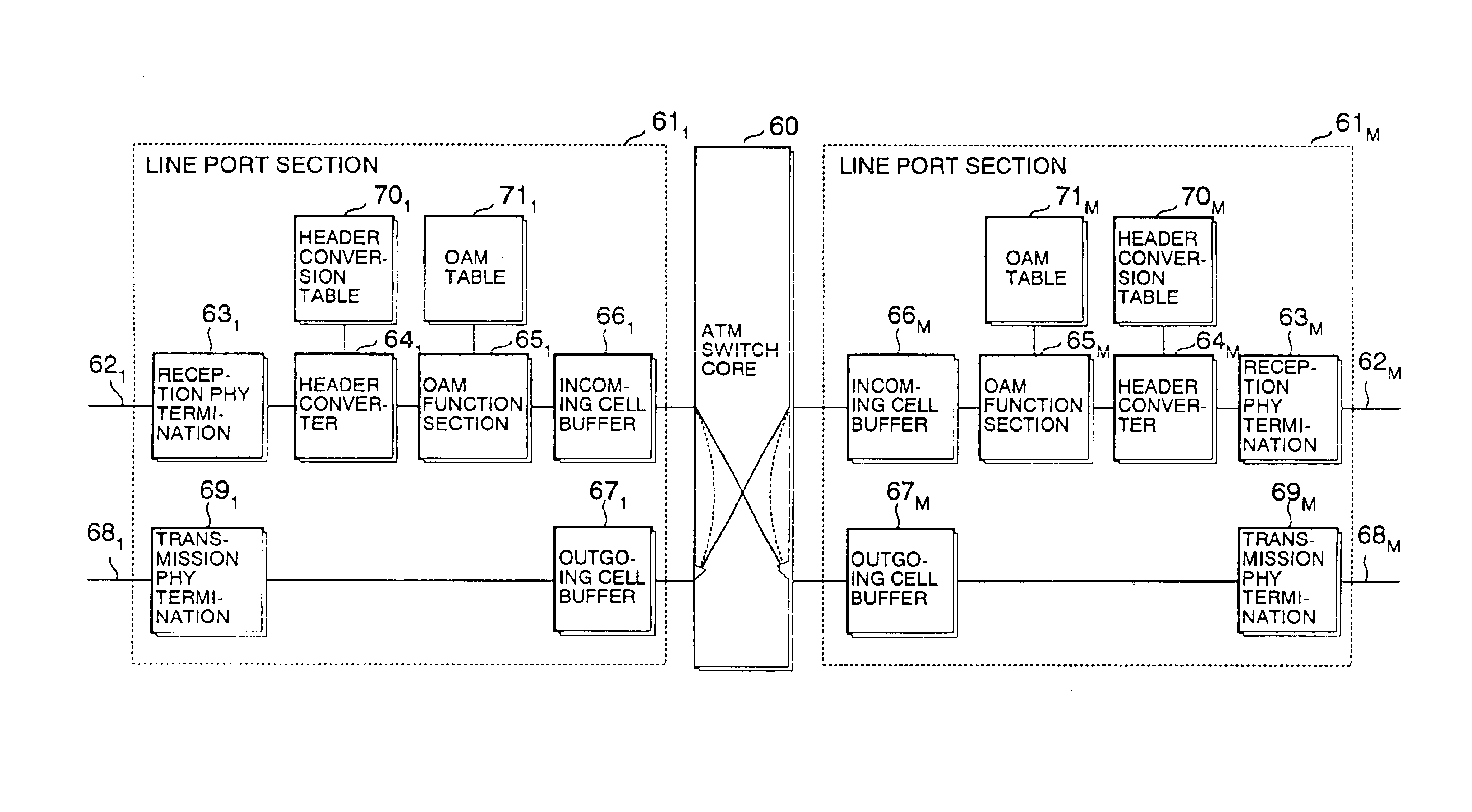
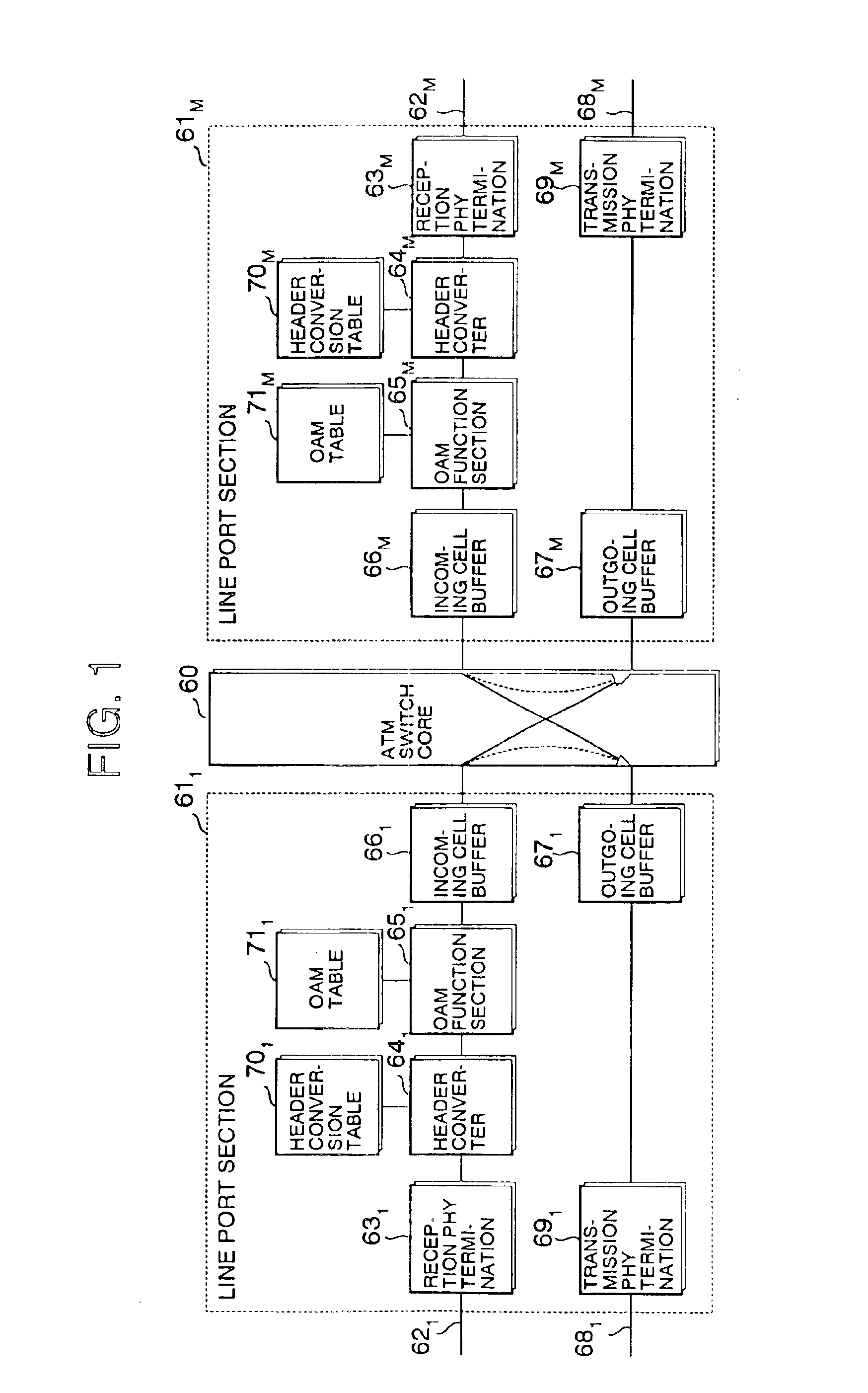
Referring to FIG. 1, an ATM switch includes an ATM switch core 60 which performs switching of ATM cells. The ATM switch core 60 has M input / output ports connected to respective ones of line port sections 611-61M, each of which has a pair of an incoming line and an outgoing line connected thereto. Here, for simplicity, only a first line port section 611 corresponding to a first port of the ATM switch core 60 and an Mth line port section 61M corresponding to an Mth port are shown.

Line Port Section

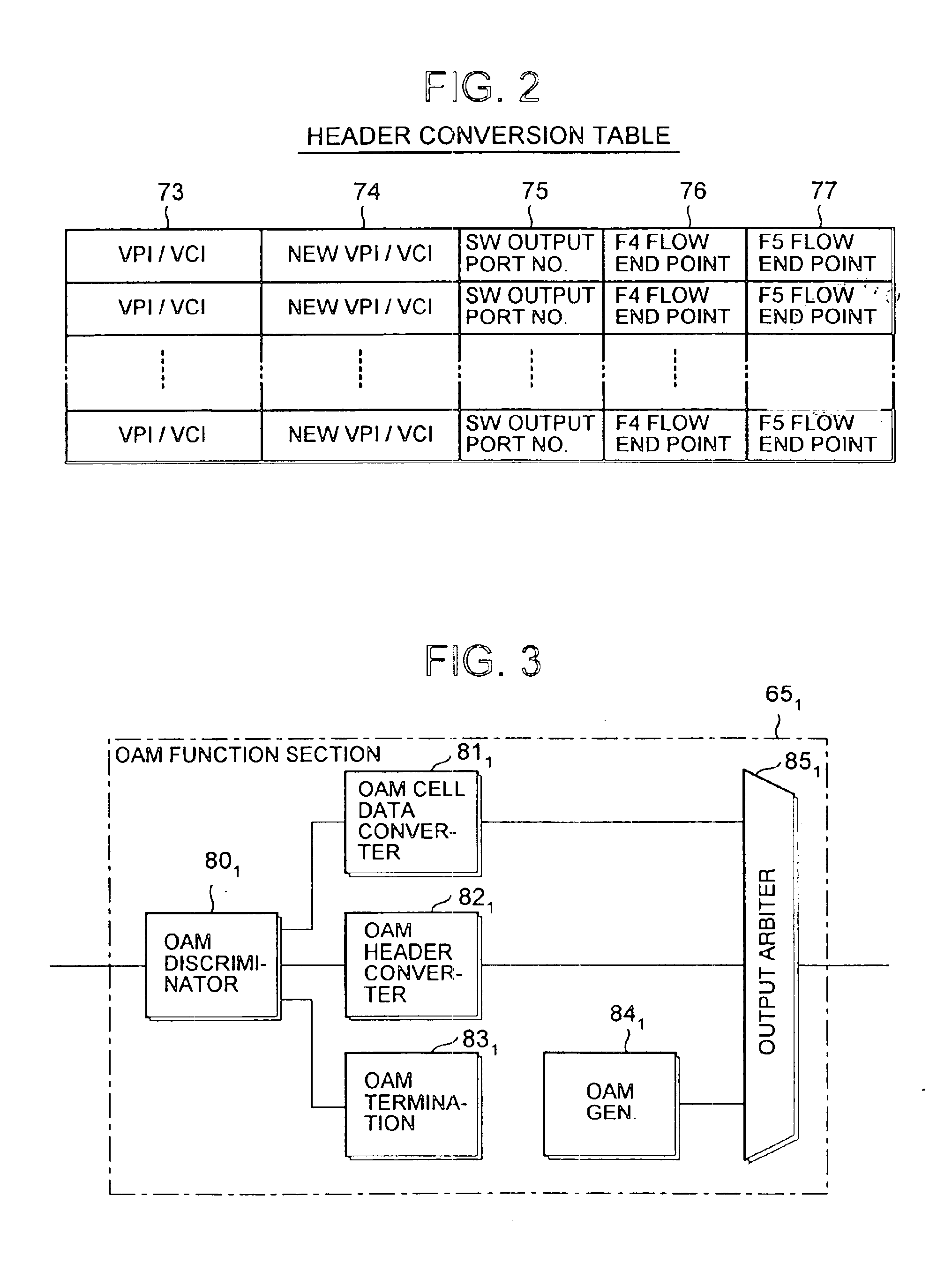
The first line port section 611 includes an incoming line circuit and an outgoing line circuit. The incoming line circuit Includes a reception side physical layer terminating portion 631 for terminating a physical layer of the reception side and receiving a cell inputted via an incoming line 621, a header converter 641 for converting the header of a cell terminated in the physical layer depending on the connection thereof, an OAM function section 651 for conducting corresponding OAM processin...


PUM


Abstract

An ATM switch allowing simplified OAM processing only on the line incoming side is disclosed. An incoming line circuit has a header conversion table storing information indicating whether the system is an end point of an OAM processing flow for each connection and an OAM table storing an AIS flag and an RDI flag for each connection. As for an OAM cell found by referring to these tables to be forced to go back to its own port, an switch output port number is rewritten in the OAM function section. In addition, in the case of an AIS cell, the function type is rewritten so as to become an RDI cell. In the case of an LB cell, the LB indication is rewritten so as to become a return LB cell, and switching to its own port is conducted in the ATM switch core.

Description

BACKGROUND OF THE INVENTION1. Field of the InventionThe present invention relates to an ATM switching system, and in particular to an ATM switch system having an operation, administration, and maintenance function.2. Description of Related ArtIn data communication using the ATM (Asynchronous Transfer Mode) technique, a fixed length packet called cell is used as a transfer unit, which allows allocation of bandwidths required for communication channels for respective ones of destinations of multimedia information such as data, audio, and video. By inserting an operation, administration, and maintenance (OAM) cell on the communication channel, OAM processing such as fault notification and connection tests can be conducted on the communication channel. The OAM processing makes optimum data communication such as reconnection and alternate connection of communication channels possible depending on the situation of the data network.As for such OAM processing, an OAM performance management ...

Claims


Application Information

Patent Timeline
IPC IPC(8): H04Q11/04H04L12/56H04L45/74H04L47/22H04L47/2466
CPCH04L49/309H04Q11/0478H04L2012/5627H04L2012/5625
Inventor IWAMOTO, HIROYUKI
Owner JUMIPER NETWORKS INC
Learn More