
Self-expanding stent with enhanced delivery precision and stent delivery system

a self-expanding, precision-enhancing technology, applied in the field of expandable endoprosthesis devices, can solve the problems of prior art delivery systems, inaccurate positioning, perforation of the vessel wall, etc., and achieve the effects of facilitating delivery, preventing longitudinal shortening of the stent during expansion, and accurate placemen

Inactive Publication Date: 2005-03-01
ABBOTT CARDIOVASCULAR
View PDF144 Cites 186 Cited by
  • Summary
  • Abstract
  • Description
  • Claims
  • Application Information

AI Technical Summary

Benefits of technology

The present invention is directed to a self-expanding stent having a configuration which permits the stent to be expanded radially to larger diameters while preventing longitudinal shortening of the stent during expansion. As a result, the present invention provides a stent which maintains a constant length from its fully compressed condition all the way through to its fully expanded condition. A self-expanding stent made in accordance with the present invention provides for more accurate placement during the delivery of the stent to the target site in the body lumen. The stent remains relatively flexible along its longitudinal axis in order to facilitate delivery through tortuous body lumens, but is strong enough radially in its expanded condition to maintain the patency of the body lumen, such as an artery or other vessel, when implanted therein.
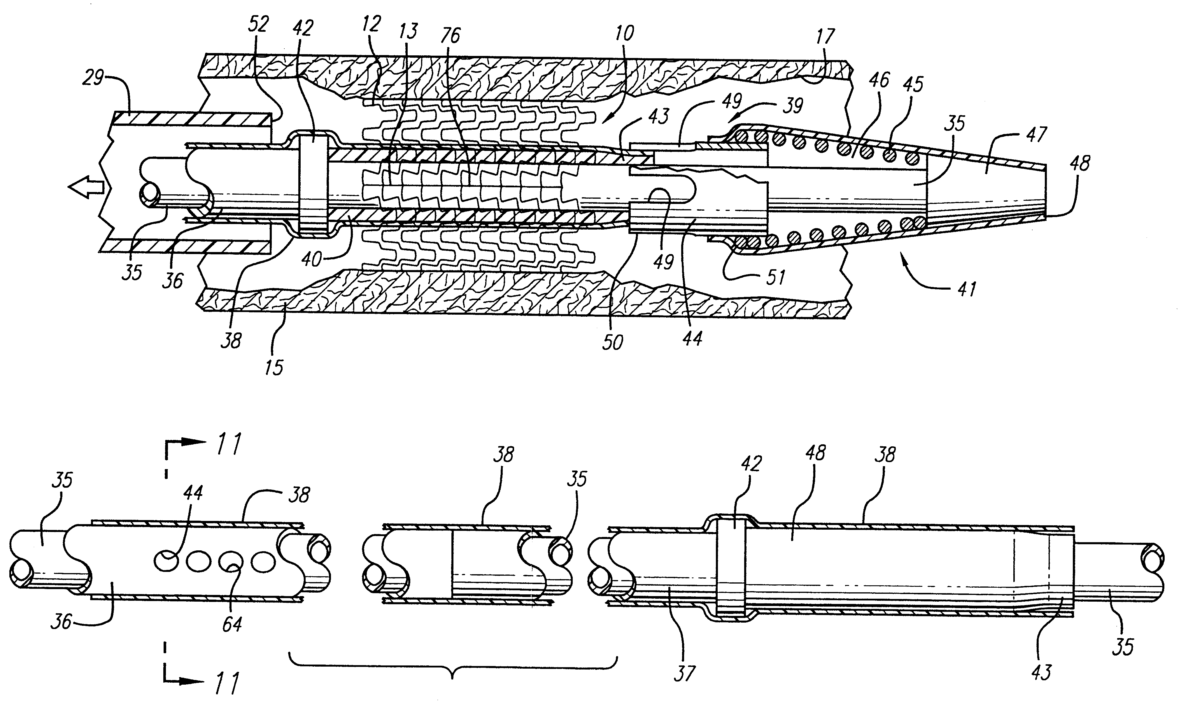
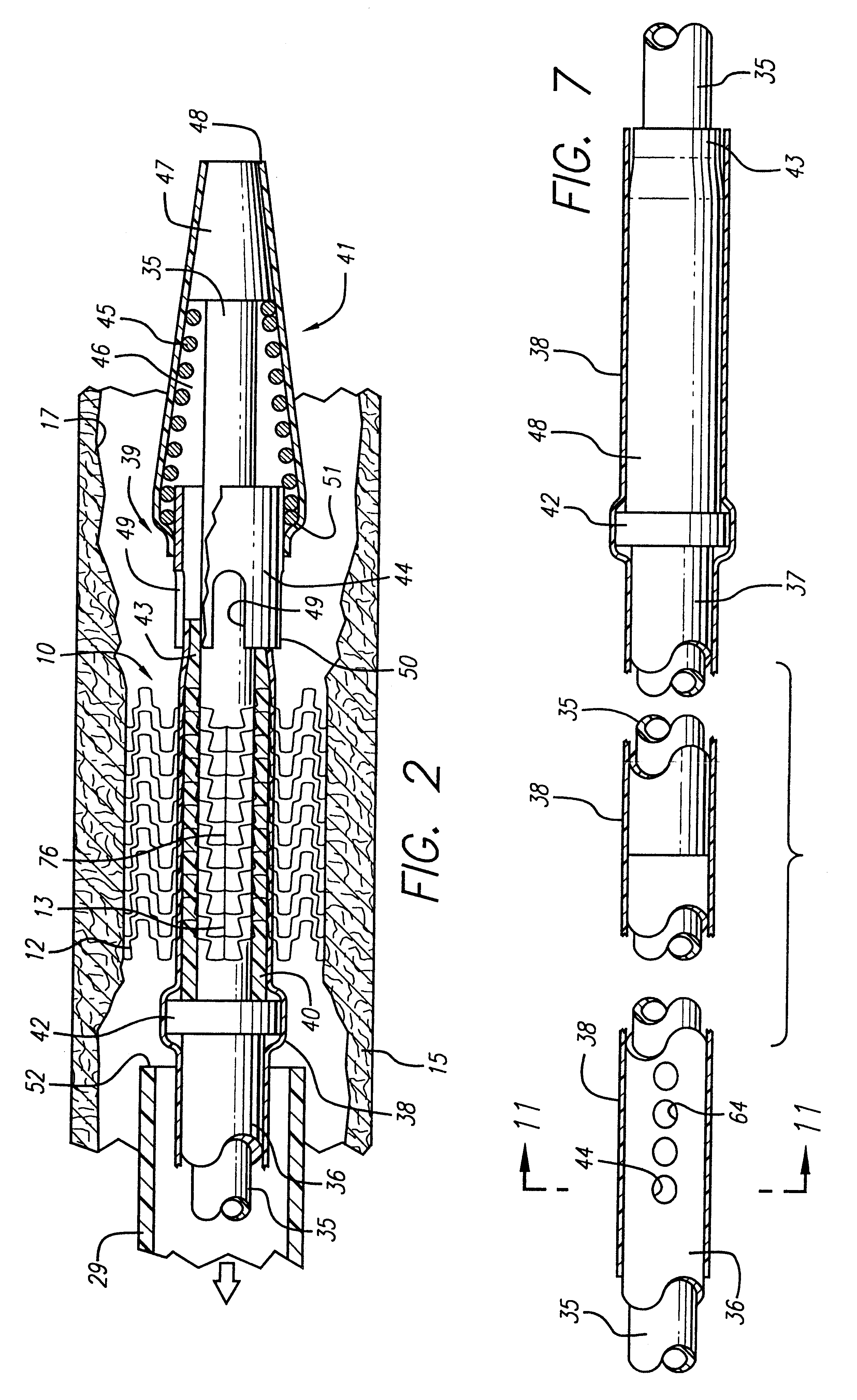
The stent delivery system of the present invention also includes a unique flushing system which is used to evacuate air from the system. The flushing system consists of small openings extending through the inner tubular member near the end of the proximal portion where it meets the distal portion of the inner member. The openings are drilled through the guide wire lumen to effectively open up a passageway from the guide wire lumen to the annular space formed between the inner tubular member and the outer tubular member. A syringe is attached to the luer fitting at the housing assembly and sterile fluid is pumped into the guide wire lumen in order to flush air from the system. A mandrel placed in the guide wire lumen at the tip assembly blocks the flow of the sterile fluid through the distal tip. The sterile fluid is thus forced to flow out of the small openings into the annular space formed between the inner tubular member and outer tubular member. The fluid flows past the collapsed stent where the fluid will eventually escape either through the small circumferential slots cut into the tubular element of the tip assembly or from the sheath directly. Once fluid is observed dripping from the end of the restraining sheath, the mandrel can be removed since air has been evacuated from the system. Since the gap sizes are so small between the various components, capillary force prevents air from infiltrating the delivery system once the evacuation has been completed.

Problems solved by technology

One of the difficulties encountered in using prior art stents involve maintaining the radial rigidity needed to hold open a body lumen while at the same time maintaining the longitudinal flexibility of the stent to facilitate its delivery and accommodate the often tortuous path of the body lumen.
However, problems have been associated with prior art delivery systems.
For example, systems which rely on a “push-pull design” can experience movement of the collapsed stent within the body vessel when the inner lumen is pushed forward which can lead to inaccurate positioning and, in some instances, possible perforation of the vessel wall by a protruding end of the stent.
As the wire is actuated, tension in the delivery system can cause the system to straighten.
This change of the geometry of the system within the anatomy can also lead to inaccurate stent positioning.
Another difficulty which can be encountered with some existing self-expanding stents is the fact that the length of the stent can shorten dramatically during deployment, making it difficult to precisely position the stent within the artery.
A self-expanding stent which shortens in length upon radial expansion of the device can cause problems to the physician attempting to accurately position the stent within the target site.
The stored energy is released as the stent expands beyond the end of the sheath, and this release of energy can cause the stent to move or “jump” from the desired position, resulting in inaccurate placement.
The above-described stent delivery systems also can be somewhat difficult to operate with just one hand, unless a mechanical advantage system (such as a gear mechanism) is utilized.
Neither of the above-described prior art stent delivery systems prevents any axial movement of the catheters of the system during stent deployment.
Even a slight axial movement of the catheter assembly during deployment can cause inaccurate placement of the stent in the body lumen.

Method used


Image

  • Self-expanding stent with enhanced delivery precision and stent delivery system
  • Self-expanding stent with enhanced delivery precision and stent delivery system
  • Self-expanding stent with enhanced delivery precision and stent delivery system

Examples


Embodiment Construction

The present invention is directed to a self-expanding stent with enhanced delivery precision and a stent delivery system for accurately placing self-expanding stents into a target site in a body lumen. While the present invention is described in detail as applied to the coronary arteries of a patient, those skilled in the art will appreciate it that it can also be used in other body lumens as well, peripheral arteries such as the carotid artery, and veins.

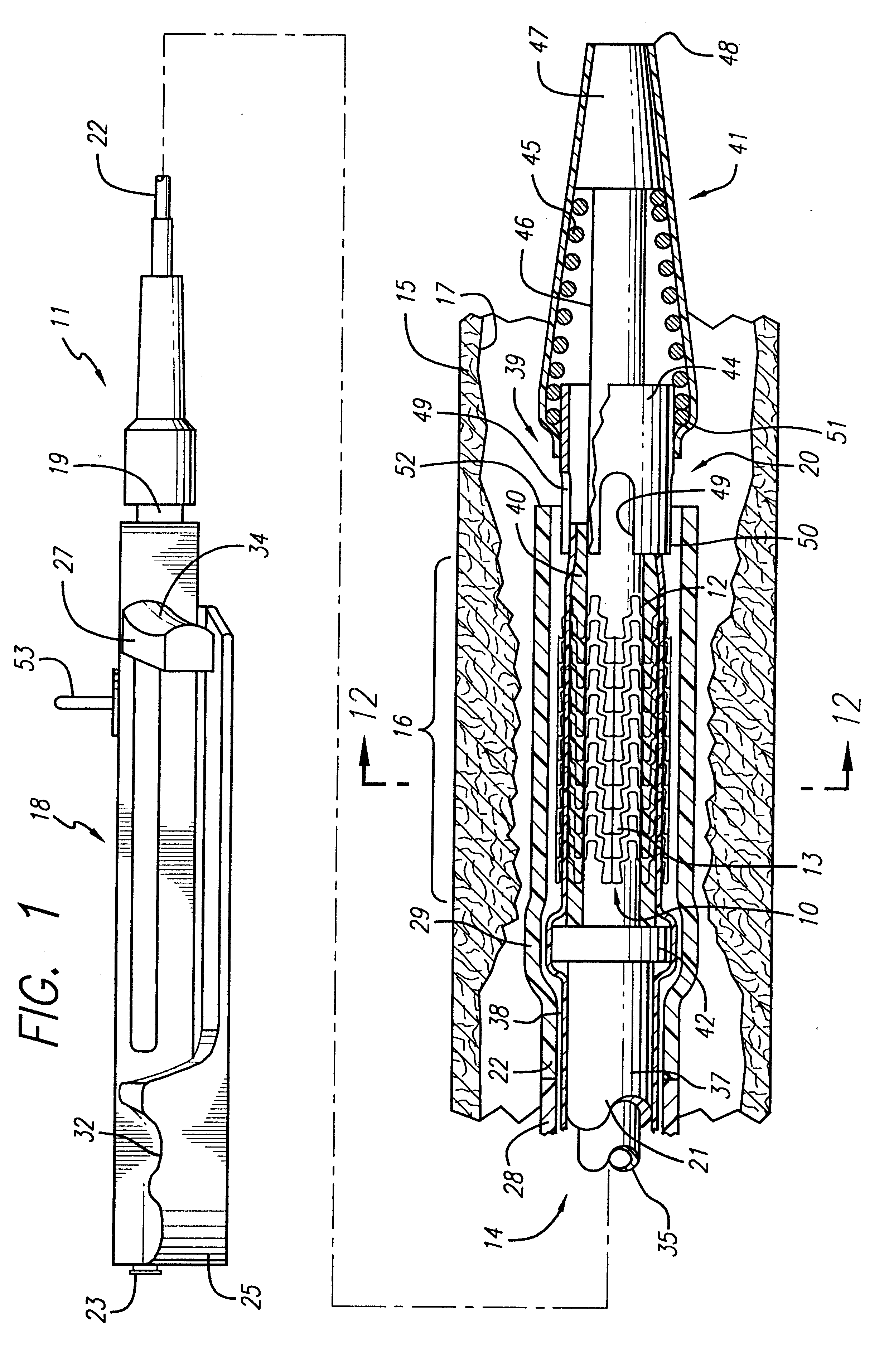
FIGS. 1-4 illustrate a self-expanding stent 10 incorporating features of the present invention. The stent 10 is mounted onto a stent delivery system 11 which is also made in accordance with the present invention. The stent 10 generally comprises a plurality of radially expandable cylindrical elements 12 disposed generally coaxially and connected by interconnecting members 13 disposed between adjacent cylindrical elements 12. Additional details regarding the particular structure and shape of the various elements making up the stent ...


PUM


Abstract

The invention is directed to a self-expanding stent for implantation into a body lumen, such as an artery. The stent consists of a plurality of radially expandable cylindrical elements generally aligned on a common longitudinal stent axis and interconnected by a plurality of interconnecting members placed on the stent in a collinear arrangement such as to create at least one continuous spine which extends along the length of the stent. The invention is also directed to a stent delivery system for implantation of a stent in a vessel which includes an outer tubular member having a restraining sheath and an inner tubular member having a distal end which has a compressed stent mounted thereto. The proximal end of the inner tubular member is connected to a housing assembly which prevents the inner tubular member from moving when the outer tubular member is retracted to deploy the stent. The proximal end of the outer tubular member is attached to a pull-back handle which is slidably mounted on the base of the housing assembly. When the pull-back handle is retracted, the restraining sheath is retracted to deploy the sheath, while the inner tubular member remains stationary.

Description

BACKGROUND OF THE INVENTIONThe present invention relates to expandable endoprosthesis devices, generally called stents, which are adapted to be implanted into a patient's body lumen, such as a blood vessel, to maintain the patency thereof, along with systems for delivering and deploying such stents. Stents are particularly useful in the treatment and repair of blood vessels after a stenosis has been compressed by percutaneous transluminal coronary angioplasty (PTCA), percutaneous transluminal angioplasty (PTA), or removed by atherectomy or other means, to help improve the results of the procedure and reduce the possibility of restenosis.Stents are generally cylindrically shaped devices which function to hold open and sometimes expand a segment of a blood vessel or other arterial lumen, such as coronary artery. Stents are usually delivered in a compressed condition to the target site and then deployed at that location into an expanded condition to support the vessel and help maintain...

Claims


Application Information

Patent Timeline
IPC IPC(8): A61F2/06A61F2/84A61F2/90
CPCA61F2/91A61F2/915A61F2/95A61F2230/0013A61F2002/91533A61F2002/91575A61F2002/9517A61F2002/91516A61F2/9517
Inventor STACK, RICHARD S.FITZ, MATTHEW J.TARAPATA, CHRISTOPHER J.
Owner ABBOTT CARDIOVASCULAR
Learn More