
I-channel surface-mount connector

a technology of surface mount connectors and connectors, applied in the direction of sustainable manufacturing/processing, electrical apparatus casings/cabinets/drawers, final product manufacturing, etc., can solve the problems of increasing the required current and power dissipation, aggravating the thermal mismatch between the connected circuit devices, and the devices for interconnecting them are subject to more demanding requirements. , to achieve the effect of low resistance, low impedance and advantageous qualities

Inactive Publication Date: 2005-03-01
POWER ONE INC +1
View PDF16 Cites 2 Cited by
  • Summary
  • Abstract
  • Description
  • Claims
  • Application Information

AI Technical Summary

Benefits of technology

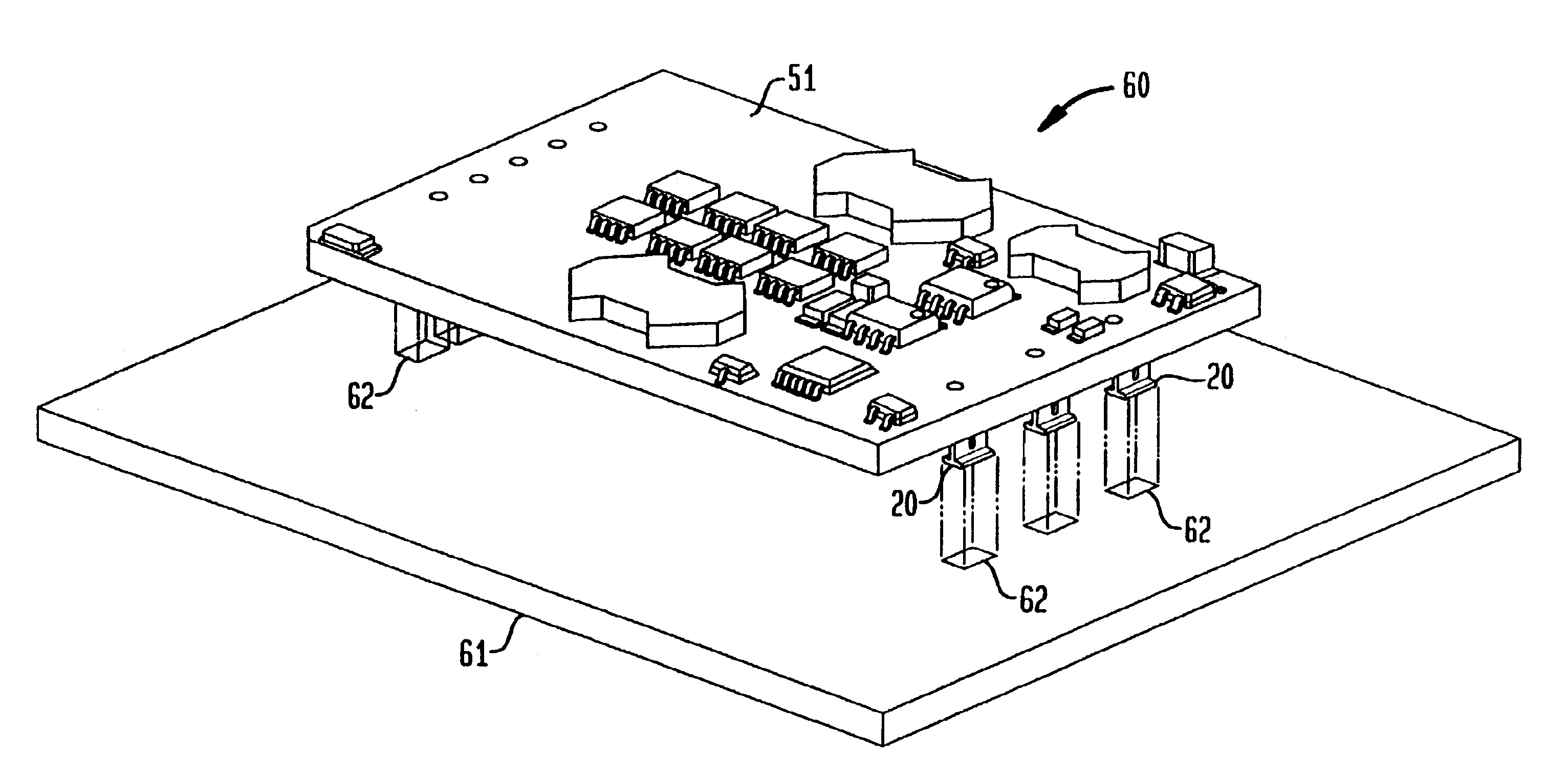
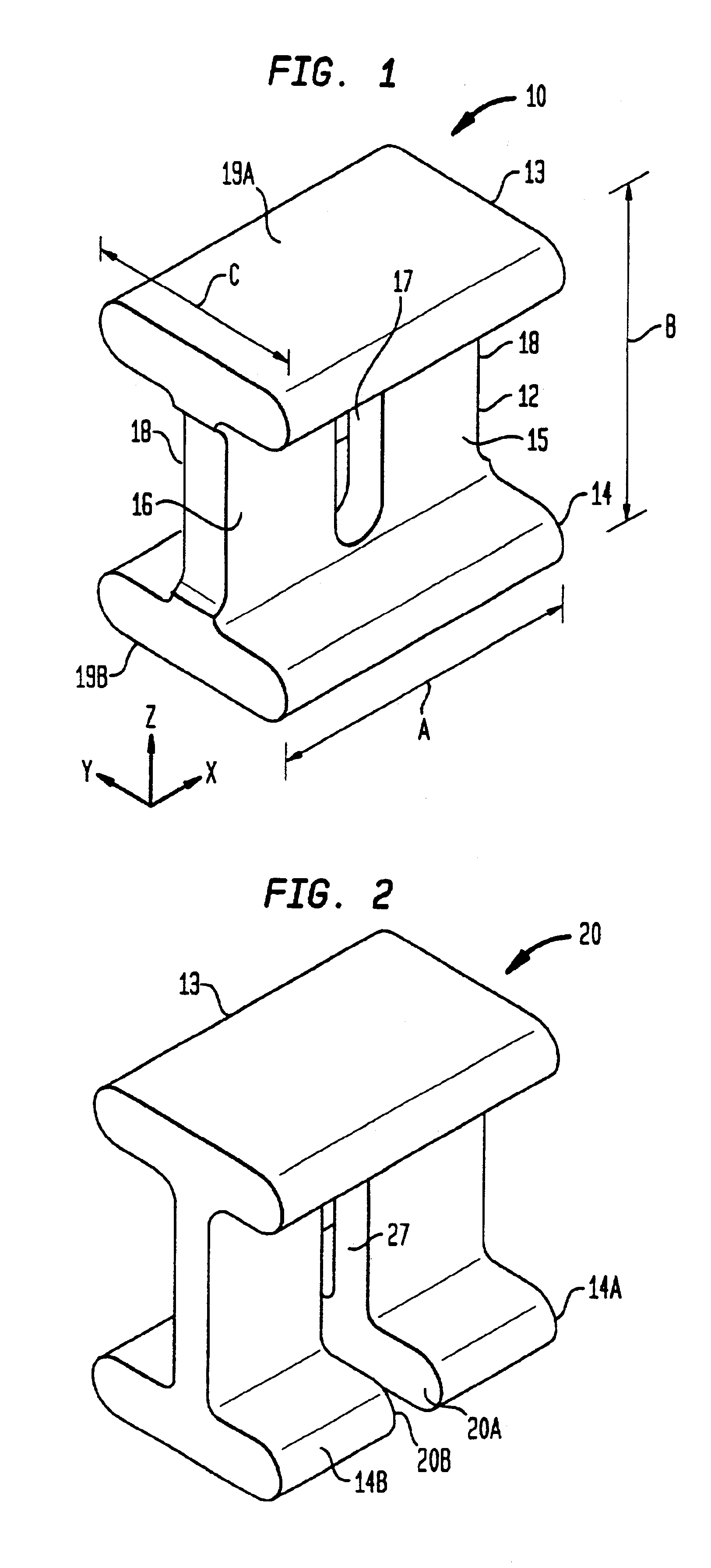
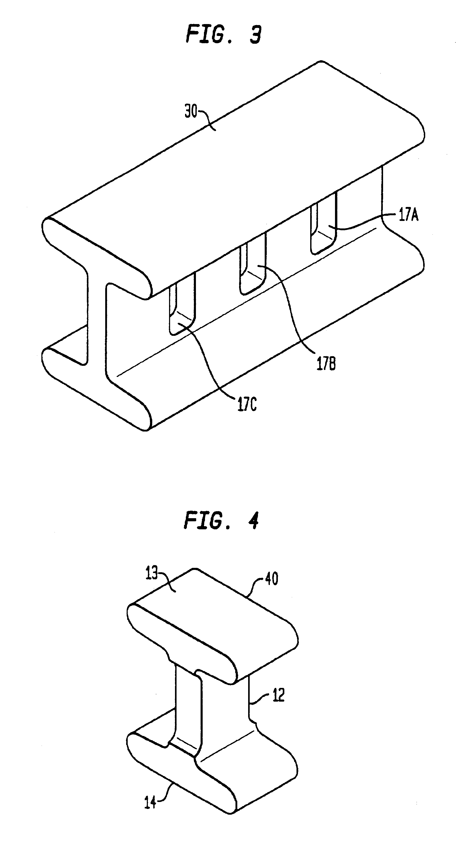
In accordance with the invention, a low impedance surface-mount connector comprises a length of cylindrical rod having an I-shaped cross section. The device permits interconnection by pick-and-place techniques, and the interconnection has advantageous qualities of low resistance, low inductance, mechanical compliance and ease of manufacture. A first circuit device having one or more circuit components is interconnected with a second circuit device by surface mounting such connectors on the first circuit device, providing corresponding solder pads on the second circuit device, and mounting the connectors of the first circuit device onto the pads of the second.

Problems solved by technology

As electronic circuits become denser, faster and increasingly complex, devices for interconnecting them are subject to more demanding requirements.
And increased density brings an increase in required currents and power dissipation, aggravating thermal mismatch between connected circuit devices.
In addition, higher circuit device speeds place stricter constraints on tolerable interconnect inductance.

Method used


Image

  • I-channel surface-mount connector
  • I-channel surface-mount connector
  • I-channel surface-mount connector

Examples


examples

The principles of the invention were used to design and fabricate devices of the type shown in FIG. 1 to meet the needs of a specific application. The application required a total of 8 surface-mount interconnects between a “circuit device” comprising a circuit board and a “motherboard” (a circuit board of larger area). The height of the tallest component on the interconnected side of the circuit device was H=0.070″. The impedance requirements, dictated by device performance needs, were that each interconnect have a maximum inductance of 0.30 nH, and a maximum resistance of 50 micro-ohm. The mechanical requirement was compliance in both X and Y directions, in the face of thermal stress caused by large differentials between the operating temperature of the circuit device and the motherboard. In addition, the area occupied by each interconnect needed to be very small, while still maintaining a minimum angle of tip of at least 30° for stability prior to reflow.

The device height B was ch...


PUM


Abstract

In accordance with the invention, a low impedance surface-mount connector comprises a length of cylindrical rod having an I-shaped cross section. The device permits interconnection by pick-and-place techniques, and the interconnection has advantageous qualities of low resistance, low inductance, mechanical compliance and ease of manufacture. A first circuit device having one or more circuit components is interconnected with a second circuit device by surface mounting such connectors on the first circuit device, providing corresponding solder pads on the second circuit device, and mounting the connectors of the first circuit device onto the pads of the second.

Description

FIELD OF THE INVENTIONThis invention relates to devices for interconnecting circuit devices such as IC packages to circuit boards, circuit boards and modules to circuit boards or substrates, and substrates to substrates. Specifically, the invention relates to low impedance surface-mount connectors having advantageous qualities of compactness, low interconnection resistance, low inductance and mechanical compliance. The connectors can be surface mounted by pick-and-place techniques.BACKGROUND OF THE INVENTIONAs electronic circuits become denser, faster and increasingly complex, devices for interconnecting them are subject to more demanding requirements. With the great increase in the density of active components, interconnection devices become large consumers of available volume. And increased density brings an increase in required currents and power dissipation, aggravating thermal mismatch between connected circuit devices. In addition, higher circuit device speeds place stricter c...

Claims


Application Information

Patent Timeline
IPC IPC(8): H01L23/498H01L23/48H05K3/36H05K3/34H01R4/02H01R12/00H01R12/52H01R12/57H05K1/14H05K5/00
CPCH01L23/49811H01R12/57H05K3/368H01R12/52Y10T29/49126H05K3/3426H05K2201/1031H05K2201/10666H05K2201/10856H01L2924/0002H01L2924/3011Y10T29/4913Y10T29/49211Y10T29/49117Y10T29/49144H01L2924/00Y02P70/50
Inventor ROY, APURBA
Owner POWER ONE INC
Learn More