
Wrapped cord

a high-engineered composite and cord technology, applied in yarn, synthetic resin layered products, transportation and packaging, etc., can solve the problems of reducing the overall strength and modulus of the cord structure, affecting the service life of the vehicle, so as to improve the fatigue resistance, the effect of high modulus and high breaking strength

Inactive Publication Date: 2005-02-15
CONTINENTAL REIFEN DEUTSCHLAND GMBH
View PDF23 Cites 22 Cited by
  • Summary
  • Abstract
  • Description
  • Claims
  • Application Information

AI Technical Summary

Benefits of technology

It has been an object of the present invention to provide a mechanism for strain dissipation and therefore fatigue resistance that does not require the conventional state-of-the-art twisting / cabling operations. In particular it has been an object of the present invention to provide a cord that combines the original yarn properties (a high breaking strength and, preferably, a high modulus) with an improved fatigue resistance.
This cord structure according to the present invention has advantages over the conventional cord that is twisted and plied in that the elimination of twisting / cabling operations saves costs and, because the core HMLS fiber is not twisted, there is no strength-loss of the core bundle in the cord. This allows fabric constructions to be modified to utilize less material to achieve the same strength and therefore reduces cost. In summary, the wrapped cord according to the present invention provides a cost-reduction for the formation of tire cord reinforcement and increased modulus while maintaining the necessary performance characteristics.

Problems solved by technology

Tires, in particular automotive tires for passenger cars or aircraft tires for aircrafts, undergo significant dynamic and static stresses and strains in the course of ordinary service life.
Performance is critical in this product application due to ramifications of failure while in use.
While the twisting results in improved fatigue performance, it lowers the overall strength and modulus of the cord structure.
In this step, the proper construction and amount of twist must be established in order to obtain the proper fatigue resistance; however, this must be balanced against the loss in strength and modulus that occurs with twisting / plying as well as the costs for imparting twist, which increase with increasing twist levels.
However, the conventional twisted cords suffer from modulus and breaking strength losses due to their helical constructions while having improved flex and compression fatigue resistance.
The losses increase with increasing twist-level or helix-angle.

Method used

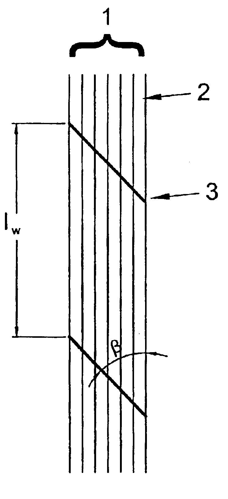
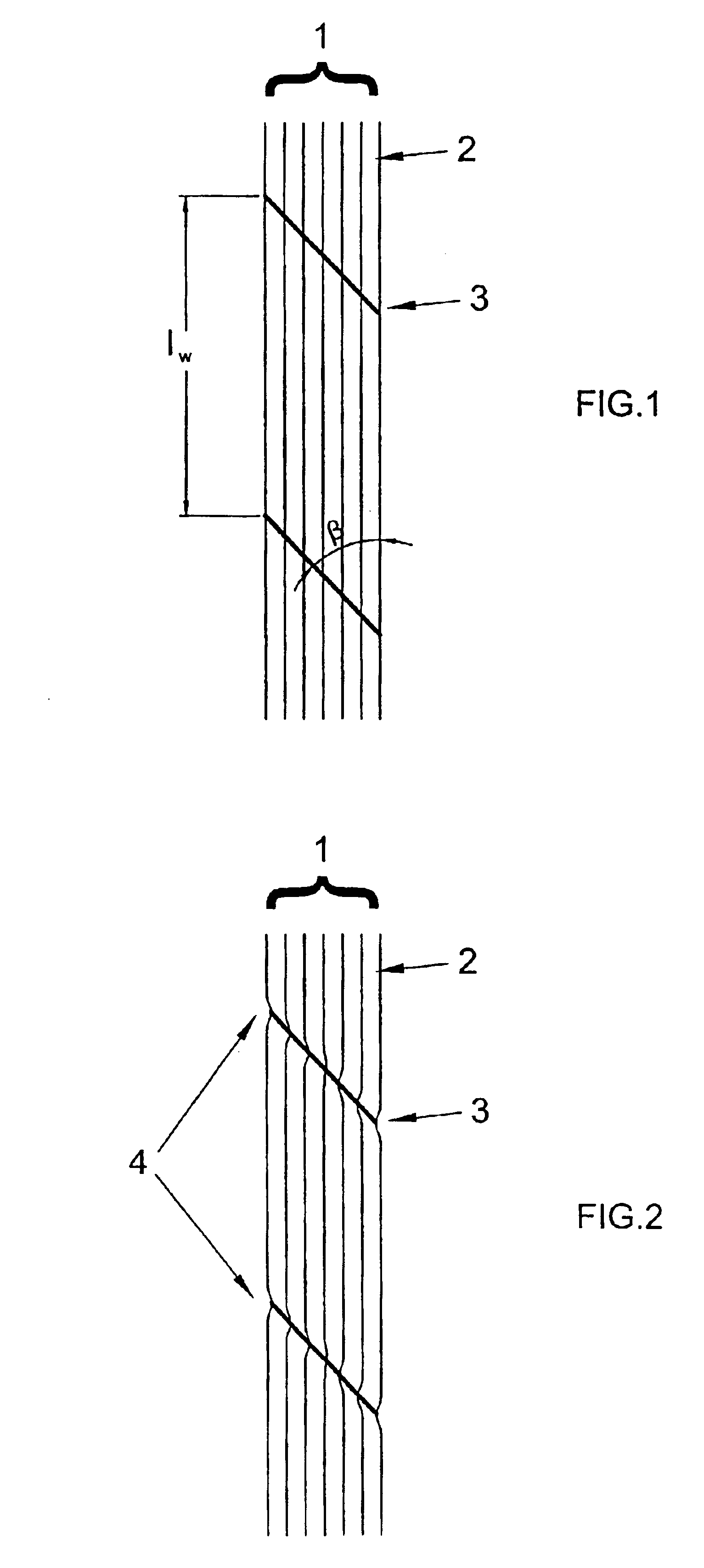
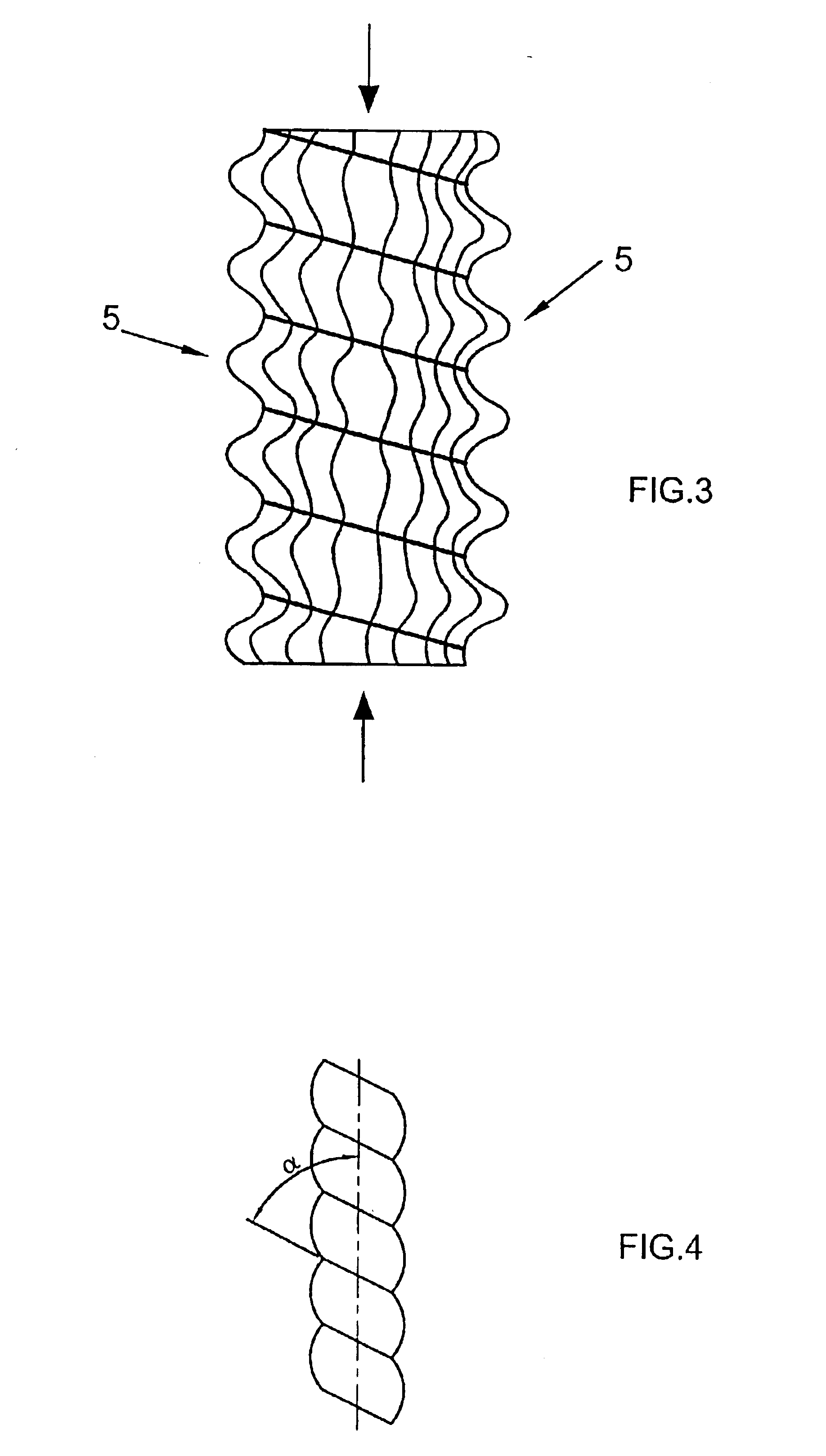

Image

  • Wrapped cord
  • Wrapped cord
  • Wrapped cord

Examples


examples

As the cord according to the present invention a 2200 dtex polyester core (D793, KoSa) and a 300 dtex shrinkable polyester as wrap from “Wire & Rapos” was used. Wraps per meter (WPM)=300.

RFL-Dip

The cord according to the present invention and the cord used for reference was treated with the following dip; after dilution with water (1 part dip A+9 parts water).

Dip ADip BVP-Latex (40%) 416.7 41.67RF-Resin (75%) 39.9%Dilution with 9  3.99parts water------------→Ammonia (25%) 11.2  1.12Formaldehyde 12.4  1.24(37%)Water 519.8 951.981000.0 g1000.0 g

The solids content of the aqueous dip composition was 2.0 weight percent. This dip with approximately 2.0% solids content has been prepared from Dip-A by diluting it with water (1 part dip A+9 parts water=Dip B).

The dips were applied to the cords by spraying dip solution but other techniques are possible as well. For instance, the adhesive can also be applied in a bath-type application, resulting in the same effect.

All cords were dried and heat ...


PUM

PropertyMeasurementUnit
Temperatureaaaaaaaaaa
Fractionaaaaaaaaaa
Fractionaaaaaaaaaa

Abstract

The present invention relates to a wrapped cord, to a method of making said wrapped cord, to a method of treating said wrapped cord with an adhesive treatment composition, to the treated wrapped cord obtainable by said method as well as to a reinforced rubber article comprising said treated cord, such as automotive tires.

Description

The present invention relates to a wrapped cord, to a method of making said wrapped cord, to a method of treating said wrapped cord with a treatment composition and to the treated wrapped cord obtainable by said method as well as to a reinforced rubber article comprising said treated cord, such as automotive tires.BACKGROUND OF THE INVENTIONA tire is a highly engineered composite designed to provide safety and durability. Tires, in particular automotive tires for passenger cars or aircraft tires for aircrafts, undergo significant dynamic and static stresses and strains in the course of ordinary service life. Performance is critical in this product application due to ramifications of failure while in use. In order to obtain the necessary performance characteristics critical to the proper functioning of a tire, structural reinforcement is a required component of the tire composite. This reinforcement provides many functions in a tire application, in particular overall strength, dimens...

Claims


Application Information

Patent Timeline
IPC IPC(8): D02G3/38D02G3/48
CPCD02G3/38D02G3/48Y10T428/2936Y10T428/2938Y10T428/2969Y10T428/2929Y10T428/2933
Inventor FIDAN, MEHMET SADETTINFORBES, CHARLES EDWARDFISHER, CHAD D.SHERRIFF, STEPHAN FREDRICKTOPP, ANDREAS
Owner CONTINENTAL REIFEN DEUTSCHLAND GMBH
Learn More