
Low pressure drop reforming exchanger

Inactive Publication Date: 2005-02-15
KELLOGG BROWN & ROOT INC
View PDF13 Cites 51 Cited by
  • Summary
  • Abstract
  • Description
  • Claims
  • Application Information

AI Technical Summary

Benefits of technology

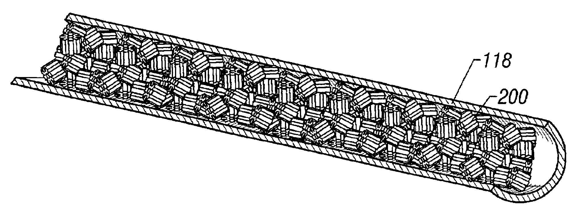
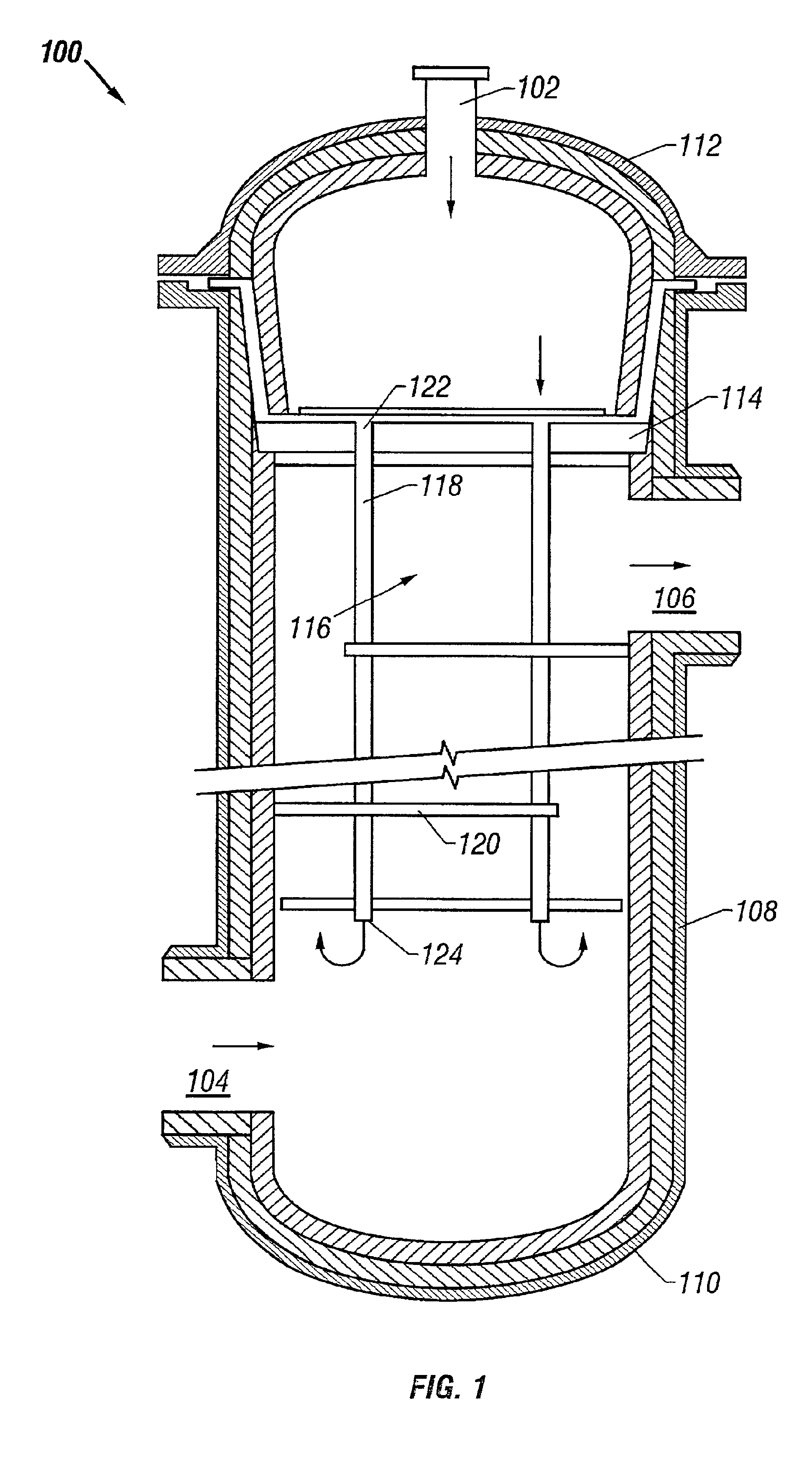
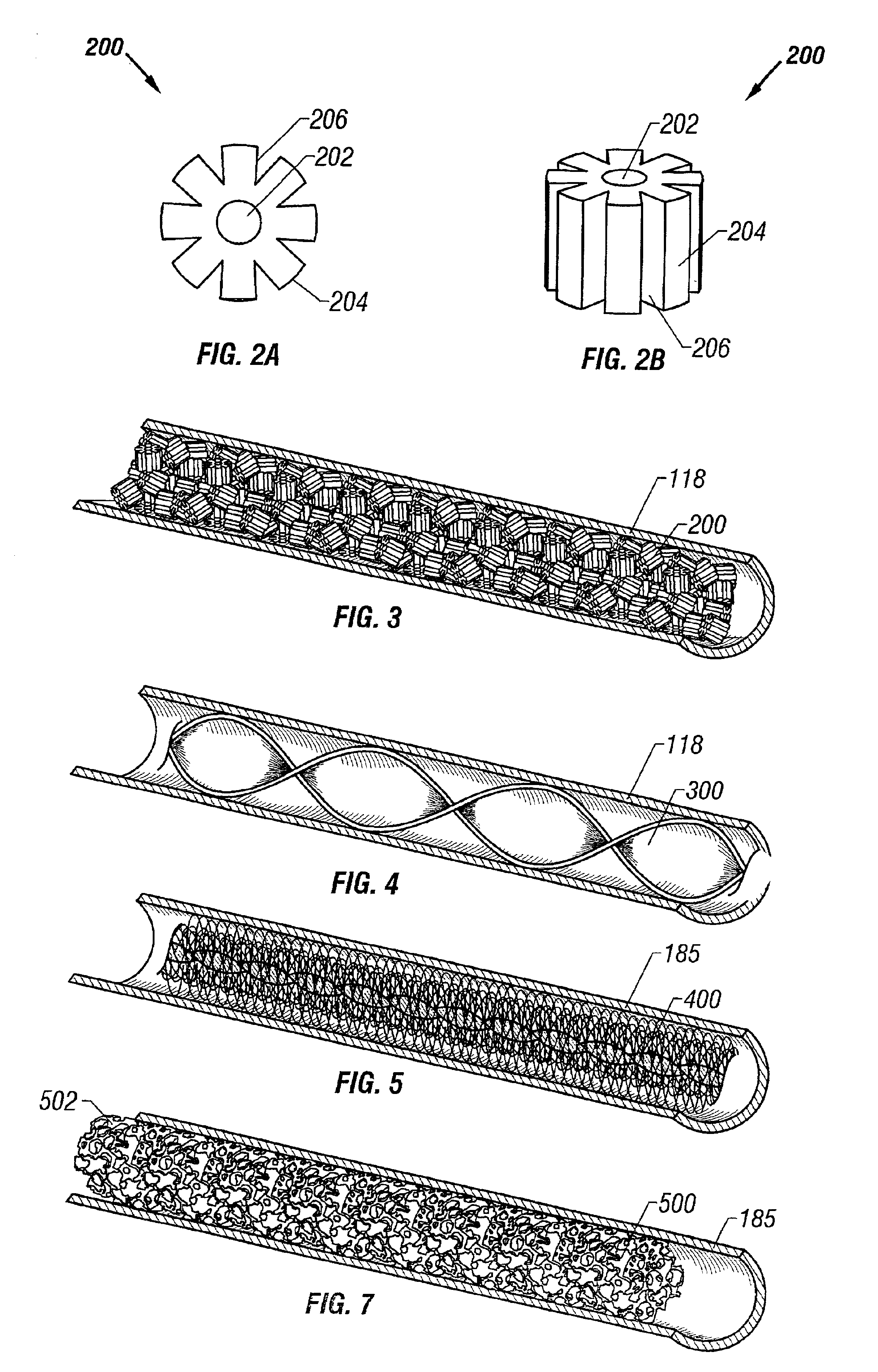
[0010]The present invention thus provides a solution to the dilemma in the prior art reforming exchanger designs. The present invention is the discovery of a tube design in a syngas reforming exchanger employing a catalyst structure and / or arrangement that allows the use of relatively long and / or relatively small-ID tubes. The catalyst-packed tubes can have a lower Dt / Dp ratio than in the prior art reforming exchangers. This allows the capacity of the reforming exchanger to be increased for a given size. Alternatively or additionally, the size and cost of the reforming exchanger for a given syngas production capacity can be significantly reduced.

Problems solved by technology

Increasing the length of the conventional catalyst-filled tubes in the existing reforming exchanger design, however, was not practical because the tube side pressure drop (ΔP) would increase beyond that permitted without unduly complicating the tube sheet and tube sheet support designs, as well as increasing upstream operating pressures and compression costs.
Furthermore, longer tubes would complicate the maintenance operations involving removal of the tube bundle.
However, it was a commonly held belief among the reforming reactor designers that the inside diameter of the heat transfer tubes had to be a minimum of 5 times the diameter or other largest edge dimension of the catalyst particles, supposedly because of packing, bridging, flow channeling, and other potential problems.
Unfortunately, the use of smaller catalyst particles in smaller tubes, to observe this conventional design criterion, resulted in an unacceptable increase in tube side pressure drop.
Conversely, because existing reforming exchanger designs were already at or near the maximum ratio of catalyst size to tube ID, the catalyst size could not be increased in the existing tube design as a means for reducing the pressure drop per unit of tube length so as to allow the use of longer tubes.
It appeared as if there would be no practical way to increase the heat transfer, and that the ultimate capacity limits of the reforming exchanger design had been reached.

Method used


Image

  • Low pressure drop reforming exchanger
  • Low pressure drop reforming exchanger
  • Low pressure drop reforming exchanger

Examples


examples

[0039]In the following examples, the tube side heat transfer coefficients, flow rates and pressure drops are based on a tube side inlet gas having the composition in Table 1:

TABLE 1ComponentMole PercentN20.23H20.34CH415.49ArCO20.03C2H61.03C3H80.34iC4H100.10iC5H120.02nC60.02CO0.00H2O82.40Total100.00

examples 1-2

[0040]Conceptual sizing reviews were done on various types of catalyst sizes and tube inserts. The catalyst was of a normal size currently used in reforming exchangers available from Kellogg Brown & Root, Inc. under the trade designation KRES (Raschig rings 0.31-in. OD by 0.125-in. ID by 0.31-in. long), a smaller catalyst size (Raschig rings 0.25-in. OD by 0.10-in. ID by 0.25-in. long), a smallest catalyst size (Raschig rings 0.185-in. OD by 0.07-in. ID by 0.185-in. long), a twisted tape insert such as a Turbulator available from Brown Fintube but made of nickel 201 (99.6% nickel), and a ceramic foam insert impregnated with nickel. The results are summarized in Table 2:

TABLE 2BaseComparativeComparativeComparativeParameterCaseExample AExample BExample CExample 1Example 2CatalystNormalSmallerSmallestSolidTwistedCeramic(0.31 ×(0.25 ×(0.185 ×Pelletstapefoam0.125 ×0.10 ×0.07 ×(0.185 ×0.31)0.25)0.185)0.185)Refractory ID1031141101204888(in.)Tube length444427246041(ft)Tube OD (in.)22.51.51....

example 3

[0043]Conceptual sizing reviews were done as in Examples 1-2 to compare the pressure drop and performance of Raschig ring catalyst against ribbed ring catalyst. Both catalyst structures measured 0.31-in. OD by 0.125-in. ID by 0.31-in. long, and the V-shaped grooves between the ribs on the ribbed ring catalyst were 0.17-in. deep. The results are presented in Table 3:

TABLE 3ComparativeParameterExample DExample 3Catalyst0.31 in. × 0.1250.31 in. × 0.125in. × 0.31 in.in. × 0.31 in.Raschig ringsribbed ringsRefractory ID (in.)5555Tube length (ft)2525Tube ID (in.)2.002.00Tube OD (in.)2.252.25Relative no. ofBase1.0tubesRelative catalystBase1.0volumeRelative surfaceBase1.0areaTube ΔP (psi)21.512.5Shell side ΔP (psi)88MTD (° F.)211225Overall U (Btu / hr-5148ft2-° F.)Approach to33.429.1equilibrium (° F.)Methane slip (%)1.191.16

[0044]The data for Example 3 demonstrate that the performance of the ribbed ring catalyst is generally equivalent to Raschig rings of the same size, except that the tube si...


PUM

PropertyMeasurementUnit
Diameteraaaaaaaaaa
Diameteraaaaaaaaaa
Diameteraaaaaaaaaa

Abstract

Syngas production process and reforming exchanger. The process involves passing a first portion of hydrocarbon feed mixed with steam and oxidant through an autothermal catalytic steam reforming zone to form a first reformed gas of reduced hydrocarbon content, passing a second portion of the hydrocarbon feed mixed with steam through an endothermic catalytic steam reforming zone to form a second reformed gas of reduced hydrocarbon content, and mixing the first and second reformed gases and passing the resulting gas mixture through a heat exchange zone for cooling the gas mixture and thereby supplying heat to the endothermic catalytic steam reforming zone. The endothermic catalytic steam reforming zone and the heat exchange zone are respectively disposed tube side and shell side within a shell-and-tube reforming exchanger. The reforming exchanger comprises a plurality of tubes packed with low pressure drop catalyst-bearing monolithic structures wherein an inside diameter of the tubes is less than 4 times a maximum edge dimension of the catalyst structures.

Description

FIELD OF THE INVENTION[0002]This invention relates to reforming exchangers for syngas production, and more particularly to reforming exchangers with catalyst tubes having a relatively low ratio of inside tube diameter to catalyst particle size.BACKGROUND OF THE INVENTION[0003]Steam reforming of a hydrocarbon to manufacture syngas is a very well known process. One popular technique is to use an autothermal reformer in conjunction with a reforming exchanger, as described in U.S. Pat. No. 5,011,625 to Le Blanc, which is hereby incorporated by reference herein in its entirety. Briefly, the hydrocarbon and an oxygen source are supplied to the autothermal reformer. The combustion reaction is exothermic and supplies the heat needed for the catalytic reforming reaction that occurs in the autothermal reformer, which is endothermic, to produce a relatively hot reformed gas. The hot gas from the autothermal reformer is then used as a heat source in the reforming exchanger, which is operated as...

Claims


Application Information

Patent Timeline
IPC IPC(8): B01J19/30B01J8/00B01J8/06B01J8/02B01J23/755B01J35/00B01J35/02C01B3/00C01B3/38
CPCB01J8/008B01J8/067B01J19/30B01J23/755B01J35/026C01B3/382C01B3/384B01J8/0292C01B2203/82B01J2208/00221B01J2208/00309B01J2208/00495B01J2208/0053B01J2219/30223B01J2219/30242B01J2219/32296C01B2203/0844C01B2203/141C01B2203/142B01J35/50B01J8/02Y02P20/52
Inventor BURLINGAME, ROBERTCZUPPON, THOMAS A.HACKEMESSER, LARRY G.
Owner KELLOGG BROWN & ROOT INC
Learn More