System and method for controlling an object detection system of a vehicle

a technology for object detection and control system, which is applied in the direction of navigation instruments, using reradiation, instruments, etc., to achieve the effects of optimizing the use of detection devices, minimizing the response time of the entire system, and stable performan

Inactive Publication Date: 2005-02-08
FORD MOTOR CO +1
View PDF9 Cites 8 Cited by
  • Summary
  • Abstract
  • Description
  • Claims
  • Application Information

AI Technical Summary

Benefits of technology

According to an embodiment of the invention, the map database is provided on-board a vehicle. This is advantageous since the time for retrieving road section attributes to the computing device is shortened as compared to an outer map database, thus contributing to minimizing the response time of the entire system. Further, the onboard location ensures continuous contact with the object detection system and thus a stable performance.
According to a further embodiment of the invention, the system is improved in that said computing device uses output from said at least one detection device as input together with said information from the on-board map database to calculate the attention plan. Such a system has the advantage that both stationary objects, which appear in the map database and in the output of the detection devices, and moving objects, which appear only in the output of the sensors, are used to optimize the use of the detection devices.

Problems solved by technology

However, due to their limited resolution capacity, one must normally select a smaller picture area within the picture frame if a better resolution of an object is needed, i.e., zooming.

Method used


Image

  • System and method for controlling an object detection system of a vehicle
  • System and method for controlling an object detection system of a vehicle
  • System and method for controlling an object detection system of a vehicle

Examples


first embodiment

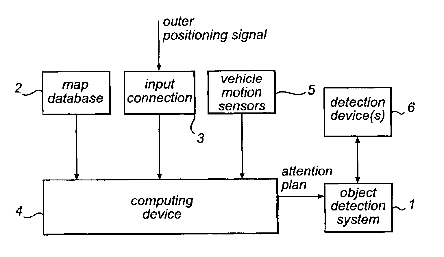
In FIG. 1, a system in accordance with the invention is shown in its working environment. The environment comprises an object detection system 1 that is associated to one or several detection devices 6 such as sensors or cameras. Most sensors have a limited geometrical operating area. This is the case with, for example, laser devices. Also, devices with a wider theoretical operating area, such as cameras, may need to be zoomed in order to retrieve a useful picture of an interesting area. In that sense, cameras also have a limited geometrical operating area.

Also, there is a map database 2 comprising information regarding road section attributes for a geographical area. Useful road section attributes are those that, for example, describe road geometry (curves and vertical curvature), lanes, intersection geometry, road signs, and other fixed obstacles that may be used for assessing in which part of the traffic environment an object being relevant for speed and steering control, obstacl...

second embodiment

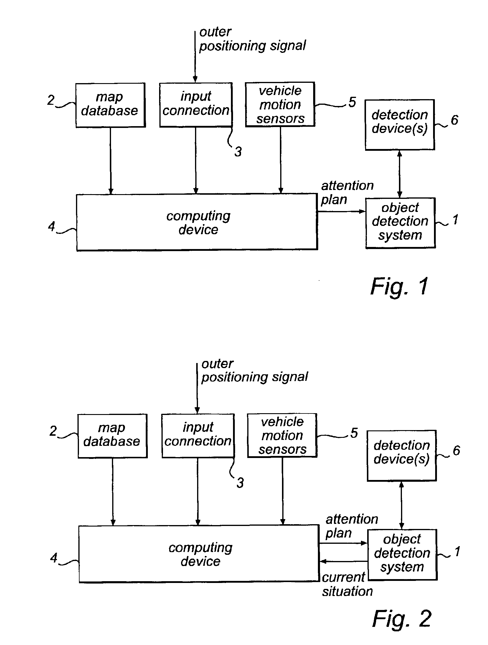
In FIG. 2, a block diagram of the invention is shown. This embodiment differs from the embodiment of FIG. 1 in that information regarding the current situation is outputted from the object detection system 1 to the computing device 4 and used for generating the attention plan. This embodiment gives an opportunity to zoom in on moving objects in the environment. In FIG. 2, like features have been given the same reference numerals as in FIG. 1.

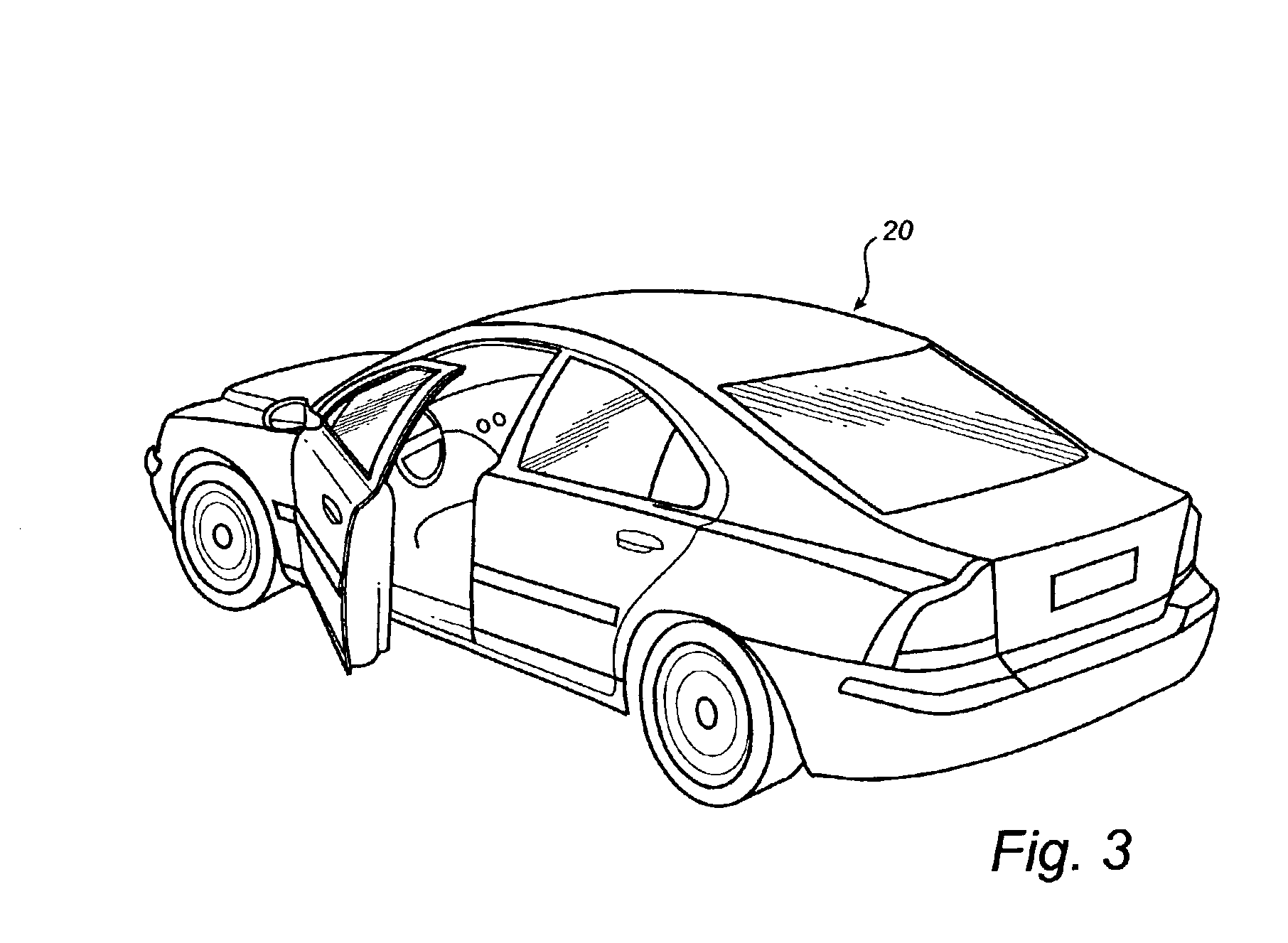
In FIG. 3 a vehicle 20 comprising said object detection system is disclosed.

A few non-limiting examples of situations where the invention may be used will be described.

Radar and laser sensors used in Adaptive Cruise Control (ACC) systems and Forward Collision Warning (FCW) systems usually have a limited scanning angle, often about 22 degrees. This allows for good function in most situations on straight highways. However, on a curved road or in combination with lane changes, the target of these systems often falls out of the active scanning angle...


PUM


Abstract

A system is disclosed for controlling an object detection system of a land based vehicle, having at least one detection device with a limited geometrical operating area. The system comprises a computing device using information regarding the current or upcoming road situation from an on-board map database as input for computing an attention plan for optimizing the use of the at least one detection device in the object detection system, said attention plan being outputted to the object detection system for control of said detection device. Further, a method is disclosed which relates to controlling an object detection system.

Description

FIELD OF THE INVENTIONThe invention relates to a system for controlling an object detection system of a vehicle, having at least one detection device with a limited geometrical operating area. It also relates to a method for controlling an object detection system.BACKGROUND OF THE INVENTIONWithin the vehicle industry, object detection systems are used for detecting objects in the environment surrounding the vehicle, such as solid or movable obstacles, other vehicles, etc. Normally, the object would be detected via one or several of a multiple of object detection sensors of the vehicle. Examples of such object detection sensors are radars, lasers, and color cameras. Also, the object detection system might include enlightenment devices or display devices that make a visual examination of the surrounding environment possible. The object detection system may connected to other systems for automatic collision warning, enlightenment steering, etc.It has also been proposed that map databas...

Claims


Application Information

Patent Timeline
Patent Type & Authority Patents(United States)
IPC IPC(8): G01C21/26G08G1/16G01S13/00G01S13/93G01S13/931
CPCB60W30/16G01C21/26G08G1/16B60T2201/08B60T2201/089B60W2550/141B60W2550/20G01S2013/9357G01S13/931G01S2013/9321B60W2550/402G08G1/166G08G1/167G01S2013/9322B60W2554/00B60W2552/05B60W2556/50
Inventor ANDERSSON, HANSAPELRYD, MARTIN
Owner FORD MOTOR CO
Why Eureka
Try Eureka