
Image distortion compensating apparatus with low switching delay

a switching delay and compensating apparatus technology, applied in the field of image distortion compensating apparatus, can solve the problems of high turn-on resistance and power consumption, large heat sinks that have to be prepared for power consumption, and the volume and weight of the image display apparatus increases, so as to minimize the switching delay of a d-class amplifier

Inactive Publication Date: 2005-02-08
SAMSUNG ELECTRONICS CO LTD
View PDF5 Cites 5 Cited by
  • Summary
  • Abstract
  • Description
  • Claims
  • Application Information

AI Technical Summary

Benefits of technology

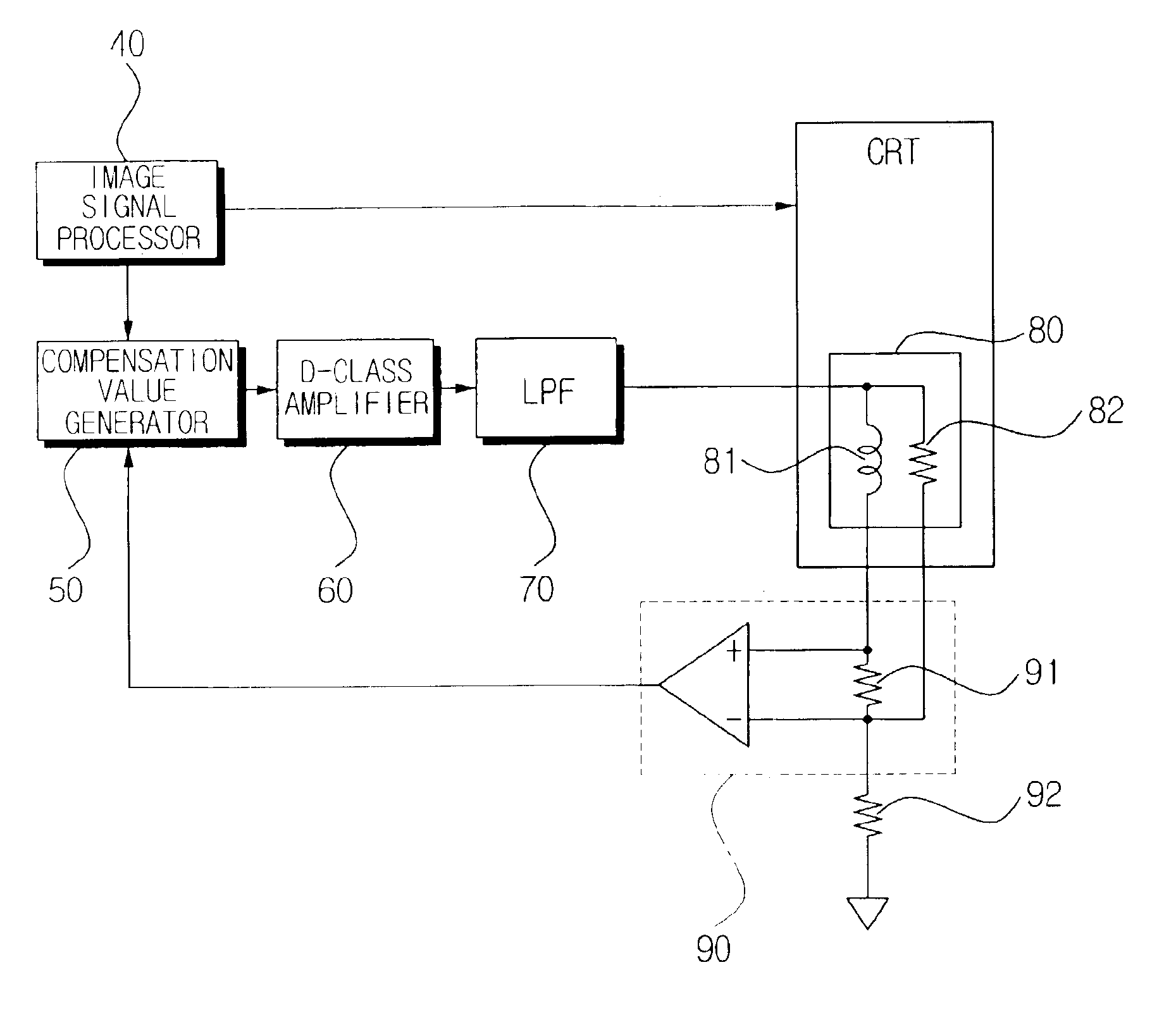
Accordingly, it is an aspect of the present invention to provide an image distortion compensating apparatus which minimizes a switching delay of a D-class amplifier.
Further provided is a feedback sensor provided between the convergence yoke and the compensation value generator, for reducing a noise outputted from the convergence yoke through a differential amplification.
Further provided is a low pass filter provided between the amplifier and the convergence yoke, for reducing the noise of the amplifier by a predetermined amount in accordance with a predetermined value.
Further provided is the step of removing a noise from an electric current forming the magnetic field.

Problems solved by technology

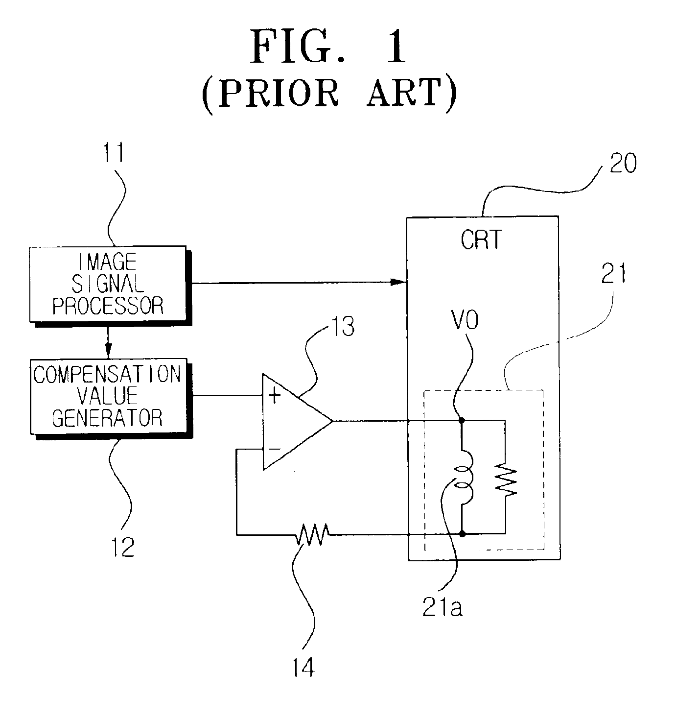
Although the power transistor has fast response and small noise during feedback of the output voltage, by its nature as an electric-driven element, it has high turn-on resistance and power consumption.
This causes one disadvantage of the operational amplifier 13 including A-, B- and C-class amplifiers that a huge heat sink has to be prepared for the power consumption.
Accordingly, volume and weight of the image display apparatus increases, and heat generated from the heat sink deteriorates safety of the system.
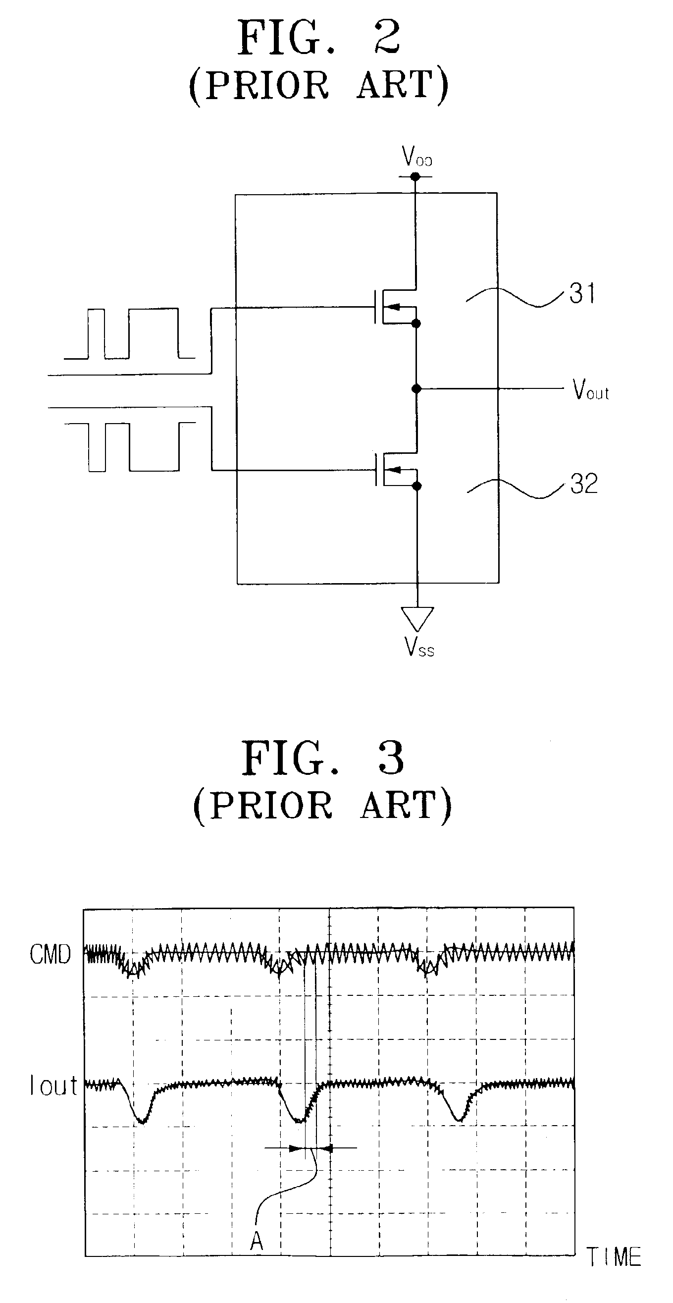
However, there is one problem of the D-class amplifier.
This causes a switching delay, which subsequently lengthens a response time during controlling on the convergence yoke with the signals as delayed.

Method used


Image

  • Image distortion compensating apparatus with low switching delay
  • Image distortion compensating apparatus with low switching delay
  • Image distortion compensating apparatus with low switching delay

Examples


Embodiment Construction

Hereinafter, the present invention will be described in detail with reference to the accompanying drawings.

FIG. 4 is a view illustrating an image distortion compensating apparatus having a compensation value generator according to a preferred embodiment of the present invention.

The image distortion compensating apparatus includes an image signal processor 40, a compensation value generator 50, a D-class amplifier 60, a low-pass filter (LPF) 70, a convergence yoke 80 and a feedback sensor 90.

The image signal processor 40 detects an image signal, a vertical and a horizontal synchronization signal from an externally received broadcasting signal. The detected image signal is transmitted to the CRT having the convergence yoke 80 built therein and displayed on the screen, while the detected horizontal and vertical synchronization signals are output through the compensation value generator 50.

The compensation value generator 50 outputs a predetermined pulse width modulating signal for driv...


PUM


Abstract

An image distortion compensating apparatus controls a convergence yoke, and includes a compensation value generator for calculating a convergence compensation value for compensating a convergence distortion which occurs while an image signal is emitted onto a display apparatus, the compensation value generator outputting the convergence compensation value after compensating for a phase and a gain of the convergence yoke; an amplifier for D-class amplifying of the convergence compensation value; and a convergence yoke attached to the display apparatus for controlling a path of electron beams corresponding to the image signal, based on the convergence compensation value as amplified at the amplifier. In the image distortion compensating apparatus used for the image display apparatus such as projection television, there is provided a D-class amplifier with high power efficiency and low heat generation, while through the two-pole and one-zero controlling, the switching delay and noise of the D-class amplifier is greatly reduced.

Description

BACKGROUND OF THE INVENTION1. Field of the InventionThe present invention generally relates to an image distortion compensating apparatus that controls a convergence amplifier, and more particularly to an image distortion compensating apparatus which reduces phase delay and noise which occur during use of a D-class amplifier. The present invention is based on Korean Patent Application No. 2002-41370, which is incorporated herein by reference.2. Description of the Related ArtGenerally, an image display apparatus such as a projection television realizes one complete image through the process of focusing images of red, blue and green images projected on a cathode ray tube (CRT). In order to focus the red, blue and green images on one spot of the CRT, a predetermined degree of electric current is applied to convergence yoke coils attached to the CRT. That is, by the predetermined electric current as applied, the magnetic field of the convergence yoke coils vary to focus the images on th...

Claims


Application Information

Patent Timeline
IPC IPC(8): H04N9/28
CPCH04N9/28
Inventor LEE, KYOUNG-GEUNROH, CHUNG-WOOKLEE, JOON-HWAN
Owner SAMSUNG ELECTRONICS CO LTD
Learn More