Push back storage rack system

a storage rack and push-back technology, applied in the field of push-back storage rack systems, can solve the problems of reducing the load-bearing capabilities of the system, limiting the number of carts that can be used and thus the number of loads that can be stored in a single lane, and reducing the design of the cart, so as to reduce the bowing or warping effect, reduce the curling and excessive warping of the beam, and prevent the end of the pallet from dragging and subsequen

Inactive Publication Date: 2005-02-08
RIDG U RAK
View PDF40 Cites 25 Cited by
  • Summary
  • Abstract
  • Description
  • Claims
  • Application Information

AI Technical Summary

Benefits of technology

The end of each cart closest to the loading end of the lane in which the cart is mounted is the trailing end of the cart and the opposite end of each cart is the leading end. When the carts are unloaded and positioned in a loading position at the loading end, the trailing end of the lowest cart rests flush against the adjacent support beam. The carts are constructed so that each successively higher cart is slightly longer than the next cart below. Following the lowest level cart of the system, a structural member at about the leading end of each successively higher cart contacts a structural member at about the leading end of the cart immediately below it when returning to the loading position. This transfers the impact force of each load to the trailing end of the lowest cart, thereby minimizing curling and excessive warping of the beam. Additionally, tensionbars positioned between approximately the middle of the structural beam and other structural members of the rack system also serve to significantly reduce the bowing or warping effect to a minimum. A push plate mounted on the trailing end of the lowest cart is offset from vertical, away from this cart, to prevent dragging on the end of pallets and subsequent damage to individual pallets and loads.
In the preferred embodiment of this invention the structural member at the leading end of each cart is an angle plate having two sections at a 90° angle to one another. The fact that each successively higher cart is slightly longer than the next lower cart enables the end of each cart's horizontal section to contact the vertical section of the cart beneath it so that the carts stack above one another without greatly adding to the vertical height needed for each additional cart. Additionally, the vertical section of each leading angle piece provides rigidity for supporting heavy loads.
At the trailing edge of each cart, relatively thin loading plates can also stack without adding a great deal of vertical height to the system. To maintain rigidity, vertical stiffeners extend downward below each loading plate, substantially along the width of the cart. For each successively higher cart, the stiffener is placed slightly further away from the cart's trailing edge than the stiffener on the cart immediately beneath it, allowing the stiffeners to remain clear of each other when the carts are stacked in the loading position.
In an optional embodiment of the design, up to four additional carts may be included in the system. In this...

Problems solved by technology

Such designs have been limited in both the number of carts that can be included in a single system and in the relative strength of each cart since the designs typically require the use of a single pair of track members and since the required horizontal clearance for successive carts prevents the inclusion of structural cross members.
Due to the resulting limitations on the amounts of available space in such designs, these characteristics have also severely limited the number of carts that can be used and thus the number of loads that can be stored in a single lane.
Additionally, smaller and weaker components may be used which substantially reduce the load-bearing capabilities of the system.
In addition to substantially limiting the system's load-bearing capacity, smaller components, such as cart wheels, also tend to increase the amount of external force necessary to operate such systems.
This ultimately leads to the need for more steeply sloped track inclines, which are undesirable, and normally increases the amount of wear and potential damage to the system, loading equipment, and stored loads.
Previous telescoping designs have been severely limited in the number of carts that can be incorporated in a single lane due to the vertical space needed to include a rigid support piece across the width of each cart.
Such cross pieces tend to make the additional vertical height required for each cart too great to incorporate many carts into a single lane.
In contrast, eliminating such piec...

Method used


Image

  • Push back storage rack system
  • Push back storage rack system
  • Push back storage rack system

Examples


Embodiment Construction

Referring to the drawings, identical reference numerals and letters designate the same or corresponding parts throughout the several figures shown in the drawings.

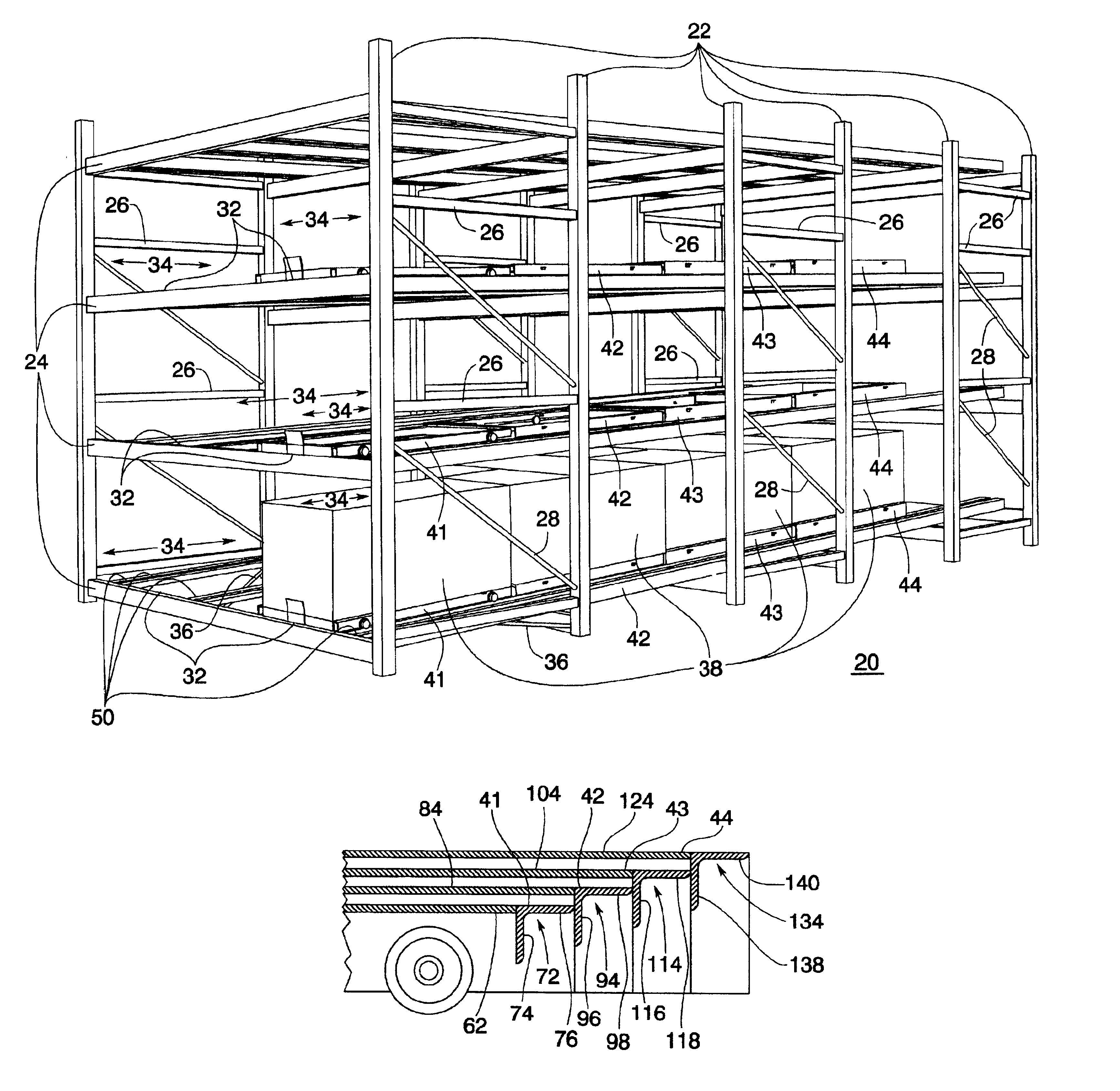
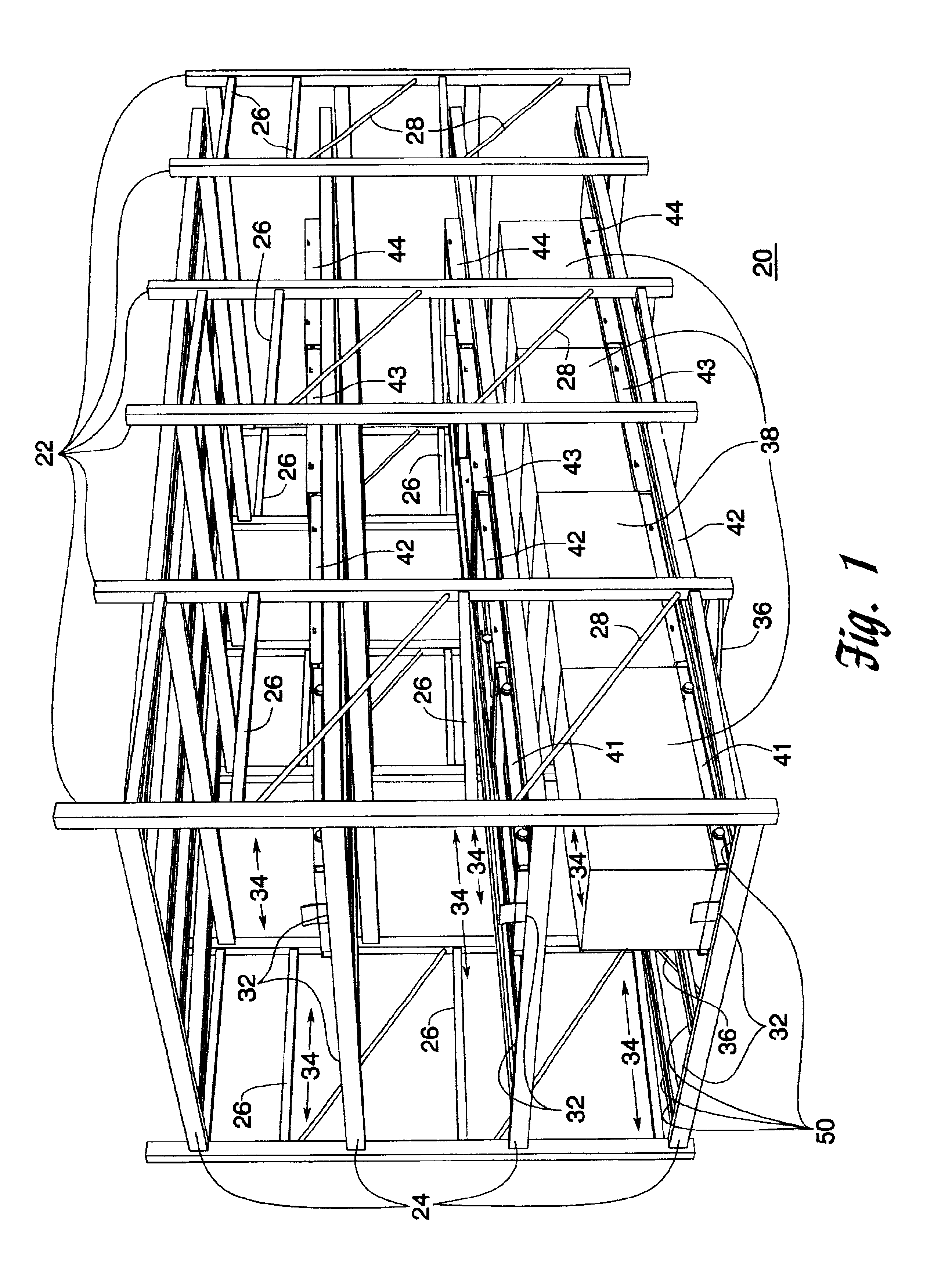
FIG. 1 shows a push back storage rack system of the type that is the subject matter of the invention. The system is based on a storage rack assembly 20 comprising a number of interconnected, vertical uprights 22 and horizontal beams 24. Side horizontals 26 and diagonal cross pieces 28 may also extend between the vertical uprights 22 to make up rack cells 30 along the depth of the rack system. Two separate cart lanes 34, each having a load end 32, are positioned along the lengths of the beams 24. To prevent the beams 24 from bowing outwardly and away from the rest of the system due to the stresses exerted on the beams 24 during operation, one or more diagonal tension bars 36 may also be positioned between about the center of one or more of the beams 24 and one or more vertical uprights 22 under the cart lanes 34. Alternativ...


PUM


Abstract

A push back storage rack system for storing multiple loads in a single inclined cart lane. Each lane contains at least two wheeled carts, each cart being capable of receiving and storing multiple pallet loads. The carts are vertically spaced so that they can freely slide underneath each other when unloaded. Beginning with the first or lowest level cart in the system, each successively higher cart is also wider and longer than the cart immediately beneath it. The carts are positioned on at least one but potentially two pairs of rectangular tracks or tubes, each tube being capable of supporting two or four individual carts, depending on how the carts are constructed and installed on the tubes. The tubes are mounted on an incline away from a loading end of each lane so that when loads are placed on or are removed from a lane, the carts are biased toward the loading end of the lane by the force of gravity. Each tube has a single, planar upper support surface which has inside and outside edges. The wheels of each cart ride only on either the inside or outside edges of the tubes on which they are mounted, allowing more than one vertically spaced cart to occupy the same tube.

Description

BACKGROUNDThe present invention is directed to the field of storage rack systems. More particularly, the present invention is directed to a push back type of storage rack system for storing a plurality of loads in which multiple loads may be stored in a single storage lane.Push back storage racks normally comprise an assembly of shelves and vertical uprights for supporting loads placed on tracks or other base members in one or more storage lanes. Each storage lane has one loading position capable of storing one load. One or more vertically spaced push back carts are positioned in the loading position. Each cart is capable of receiving one load, being pushed toward the back of the lane by the next load, and sliding over the top of one another when unloaded. Such systems normally have their tracks in each lane tilted toward the loading position so that the force of gravity causes the next cart in line to return to the loading position when a load occupying the position is removed.When...

Claims


Application Information

Patent Timeline
IPC IPC(8): B65G1/02B65G1/08
CPCB65G1/026
Inventor GORNIAK, THEODORE S.PELLEGRINO, JOHN B.COURTWRIGHT, JAMES A.
Owner RIDG U RAK
Why Eureka
Try Eureka