
Control apparatus and control method for a forklift and forklift

Inactive Publication Date: 2005-02-01
NIPPON YUSOKI
View PDF10 Cites 16 Cited by
  • Summary
  • Abstract
  • Description
  • Claims
  • Application Information

AI Technical Summary

Benefits of technology

Accordingly, an object of the invention is to provide a control apparatus and a method for a forklift that can regenerate and effectively use potential energy at the time of the lift down operation of a fork and control the lift-down speed of the forks to a desired speed accurately.
In contrast, when it is determined to be the regeneration state at the time of the lift-down operation, the change-over member is changed over so as to couple the lift cylinder to the hydraulic motor thereby to control the hydraulic motor. Thus, the potential energy of the forks and the potential energy of a baggage can be regenerated and utilized effectively.
The operation amount detector may be formed by a potentiometer for detecting operation amounts of the lift lever operated to a lift-up side and to a lift-down side. According to such a configuration, the potentiometer can detect whether the lift lever is operated to the lift-up side or to the lift-down side and also can detect the operation amount of the lift lever accurately.
According to such a configuration, when the operation of the operation lever different from the lift lever is detected by the operation detector, the determining means determines that it is the non-regeneration state irrespective of the torque command value. Thus, the oil can be supplied from the hydraulic pump to the cylinder different from the lift cylinder without causing any trouble, so that there is no fear that the working efficiency is degraded.
In contrast, when it is determined to be the regeneration state at the time of the lift-down operation, the lift cylinder is coupled to the hydraulic motor thereby to control the hydraulic motor by using the inverter. Thus, the potential energy of the forks and the potential energy of a baggage can be regenerated and utilized effectively.

Problems solved by technology

Thus, this potential energy is wasted.
In particular, when a baggage is loaded on the fork 1, since the weight of the baggage is added to the dead weight of the fork 1, the potential energy becomes very large.
Thus, particularly, in the fully opened state of the lift valve 7, there arises a problem that it is difficult to control the speed at the lift-down operation to a desired speed.
However, in the case of using the DC motor, since a regeneration control circuit is required in addition to a normal driving control circuit, the configuration of the control circuit becomes complicated and expensive.
Thus, there arises an inconvenience that although the potential energy can be utilized, economical efficiency is degraded.

Method used


Image

  • Control apparatus and control method for a forklift and forklift
  • Control apparatus and control method for a forklift and forklift
  • Control apparatus and control method for a forklift and forklift

Examples


Embodiment Construction

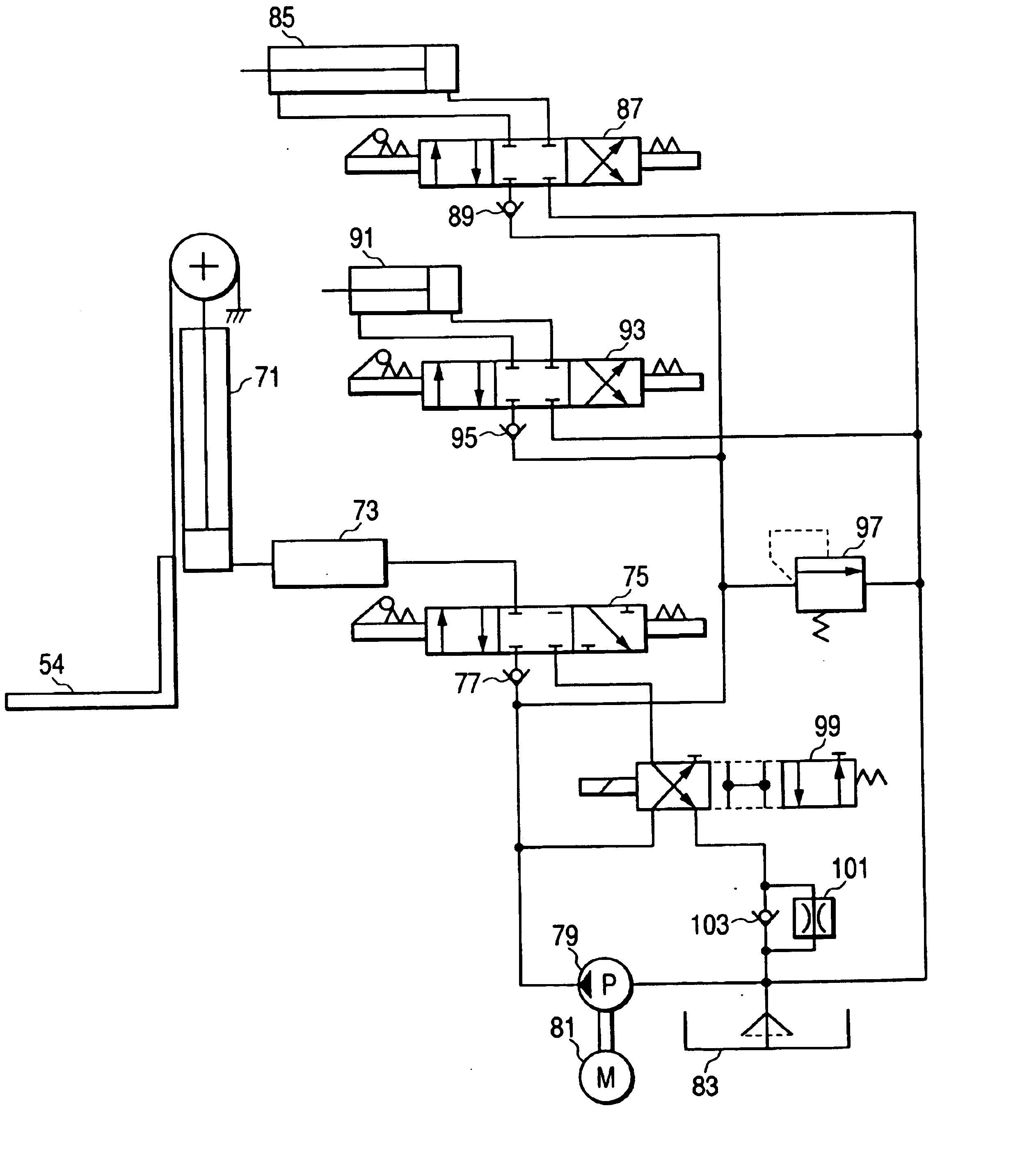
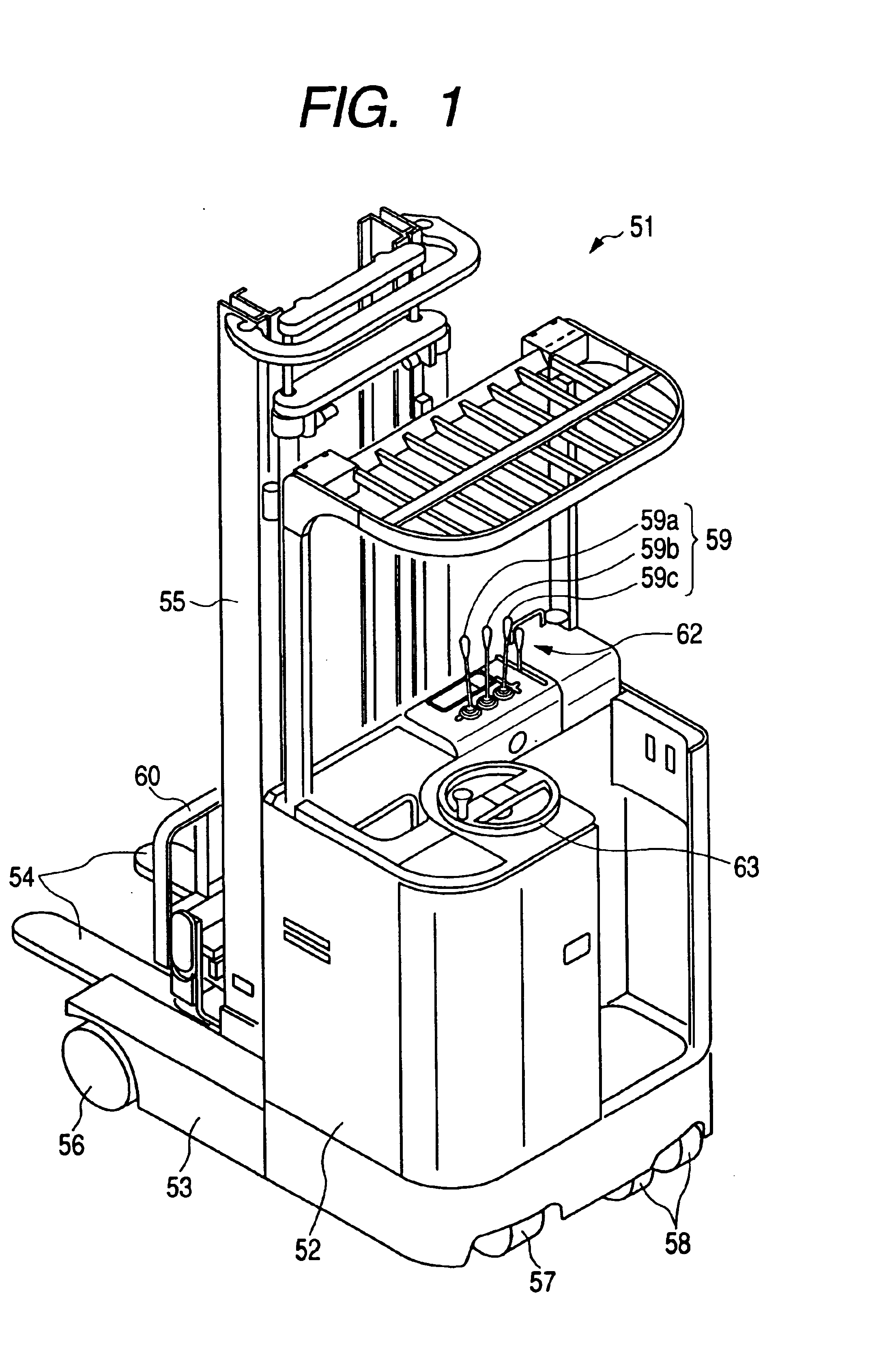
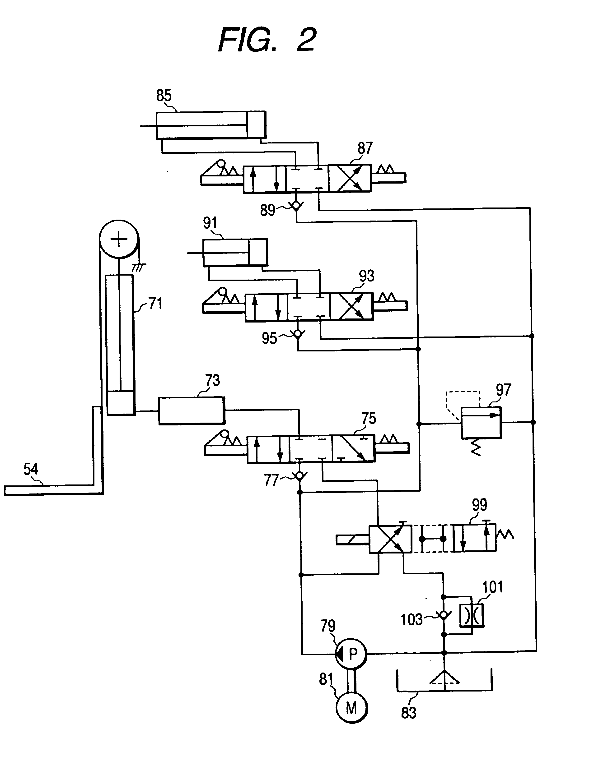
An embodiment to which the invention is applied to a reach type forklift will be explained with reference to FIGS. 1 to 5. FIG. 1 shows a perspective view of the reach type forklift, FIG. 2 is a hydraulic circuit diagram of the reach type forklift shown in FIG. 1, FIG. 3 is a block diagram of a control system, FIGS. 4A and 4B are diagrams for explaining the operation thereof and FIG. 5 is a flow chart for explaining the operation thereof.

The reach type forklift according to the embodiment is configured as shown in FIG. 1. Pair of straddle arms 53 are fixed so as to protrude forward at left and right ends of the front portion of a vehicle body 52 of the reach type forklift, respectively. A mast 55, on which a lift cylinder 71 (not shown in FIG. 1) is disposed, is provided between the straddle arms 53 so as to be able to move forward and backward. Pair of L-shaped forks 54, which are lifted up and down by the lift cylinder 71, are guided by the mast 55 through a tilt bracket 60.

Left a...


PUM


Abstract

A control apparatus includes a target acceleration obtaining device for obtaining a target acceleration of a hydraulic motor based on an operation amount of a lift lever; a torque command value obtaining device for obtaining a torque command value of a hydraulic motor based on the target acceleration; a determining device for determining as a non-regeneration state or as a regeneration state based the torque command value; and a change-over control device for changing over a change-over member so as to couple a lift cylinder to a flow rate control valve when determined as the non-regeneration state, and for changing over the change-over member so as to couple the lift cylinder to a hydraulic pump and making an inverter controller control the hydraulic motor in accordance with the torque command value when determined as the regeneration state.

Description

BACKGROUND OF THE INVENTION1. Field of the InventionThe present invention relates to a control apparatus and a method for a forklift provided with a hydraulic pump and a hydraulic motor for operating a lift cylinder for lifting up and down a fork.2. Description of the Related ArtConventionally, as a cargo apparatus for a forklift used for loading and unloading a baggage, ones being operated by hydraulic pressure have been employed. The hydraulic circuit of such a cargo apparatus is configured as shown in FIG. 6, for example. That is, a lift cylinder 3 for lifting up and down a fork 1 is coupled to a hydraulic pump 9 through a fuse valve 5 and a lift control valve (hereinafter called as a lift valve) 7 which is changed over between a lift-up side (the left side in FIG. 6) and a lift-down side (the right side in FIG. 6) by the operation of a lift lever. The hydraulic pump 9 is driven by a hydraulic motor 11, whereby oil reserved within an oil tank 13 is supplied to the lift cylinder 3...

Claims


Application Information

Patent Timeline
IPC IPC(8): B66F9/22B66F9/24B66F9/20F15B11/00F15B21/00F15B21/14F15B11/024F16H61/40F16H61/4096
CPCB66F9/22F15B11/024F15B21/14B66F9/24F15B2211/75F15B2211/20515F15B2211/30505F15B2211/30525F15B2211/3058F15B2211/3111F15B2211/31576F15B2211/324F15B2211/40507F15B2211/40584F15B2211/41527F15B2211/41581F15B2211/428F15B2211/46F15B2211/50518F15B2211/55F15B2211/7052F15B2211/7053F15B2211/71
Inventor CHEN, SHUMING
Owner NIPPON YUSOKI
Learn More