
Method and apparatus for reducing speckle in optical coherence tomography images

a technology speckle reduction, applied in the field of optical coherence tomography, can solve the problems of not being able to distinguish coherent msl from light from a region of interest (roi) in a sample, the total field will add destructively and be dark, and achieve the effect of simple and inexpensive speckle reduction system and method, without loss of optical resolution or reduction in image acquisition speed

Inactive Publication Date: 2005-01-25
THE UNITED STATES OF AMERICA AS REPRESENTED BY THE SECRETARY OF THE NAVY
View PDF13 Cites 89 Cited by
  • Summary
  • Abstract
  • Description
  • Claims
  • Application Information

AI Technical Summary

Benefits of technology

The present invention provides a simple and inexpensive system and method for reducing speckle in optical coherence tomography (OCT) images without loss of resolution or image acquisition speed. The method involves averaging over different angles of incident light while maintaining a constant optical path length to discriminate against speckle caused by coherent multiply scattered light (MSL). The invention improves the quality of OCT images and detectability of sub-surface structures of a sample. The apparatus includes a lens for focusing incident light, a processor for reducing speckled noise, and an optical device for collecting backscattered light from the sample.

Problems solved by technology

At some points, the total field reflecting from the material will add constructively and be bright, while at other points the total field will add destructively and be dark.
The problem of speckle is especially serious in the detection of internal structures, for which the spatial scale of the speckle is comparable with that of defects in the material, such as for example, subsurface cracks in ceramics.
While OCT discriminates against incoherent multiply scattered light (MSL), it fails to discriminate coherent MSL from light from a region of interest (ROI) in a sample.
Although the above techniques will reduce speckle from a ROI as well as from MSL, the penalty paid for the speckle averaging is the loss of optical resolution and also slower image acquisition.
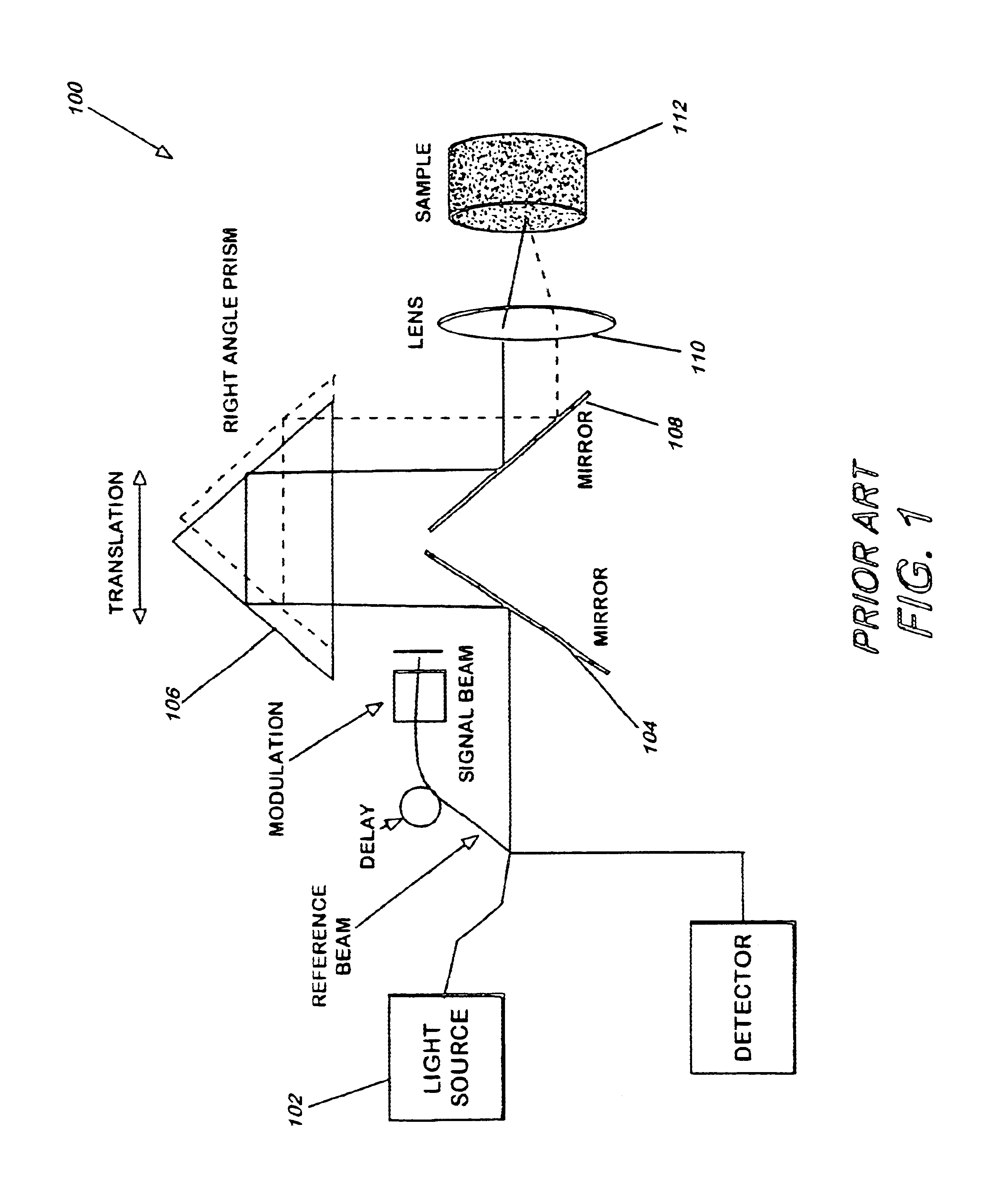
Although the apparatus shown in FIG. 1 reduces speckle from a ROI as well as from coherent MSL, the penalty paid for speckle averaging is the loss of optical resolution and slower image acquisition.
The loss of resolution occurs because angle averaging requires that the input beam not fill the lens.
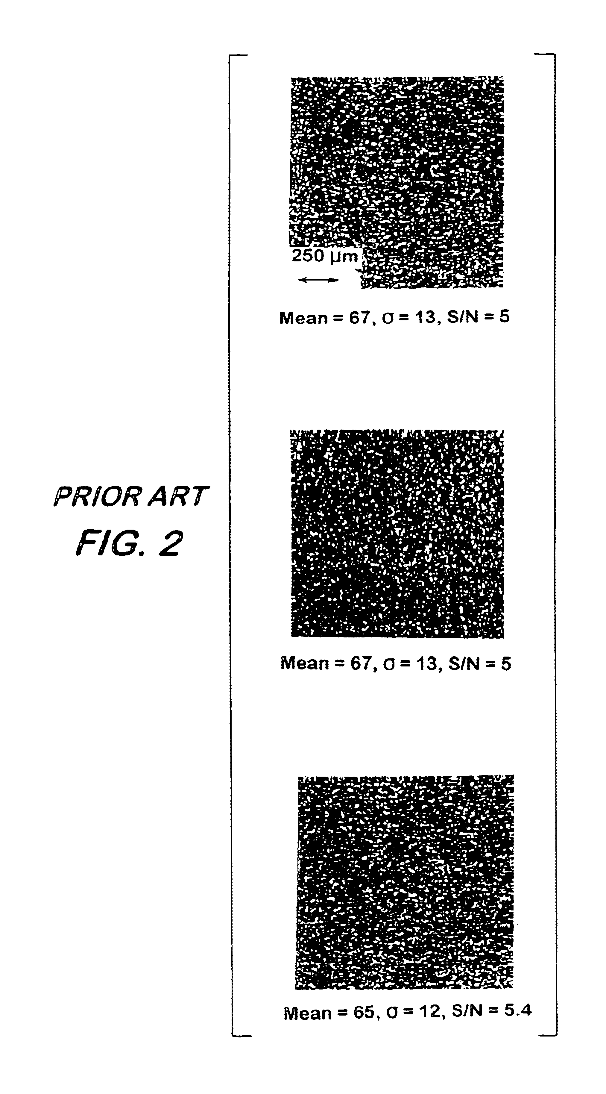
The speckled appearance of the images represents a significant difficulty in crack detection.

Method used


Image

  • Method and apparatus for reducing speckle in optical coherence tomography images
  • Method and apparatus for reducing speckle in optical coherence tomography images
  • Method and apparatus for reducing speckle in optical coherence tomography images

Examples


Embodiment Construction

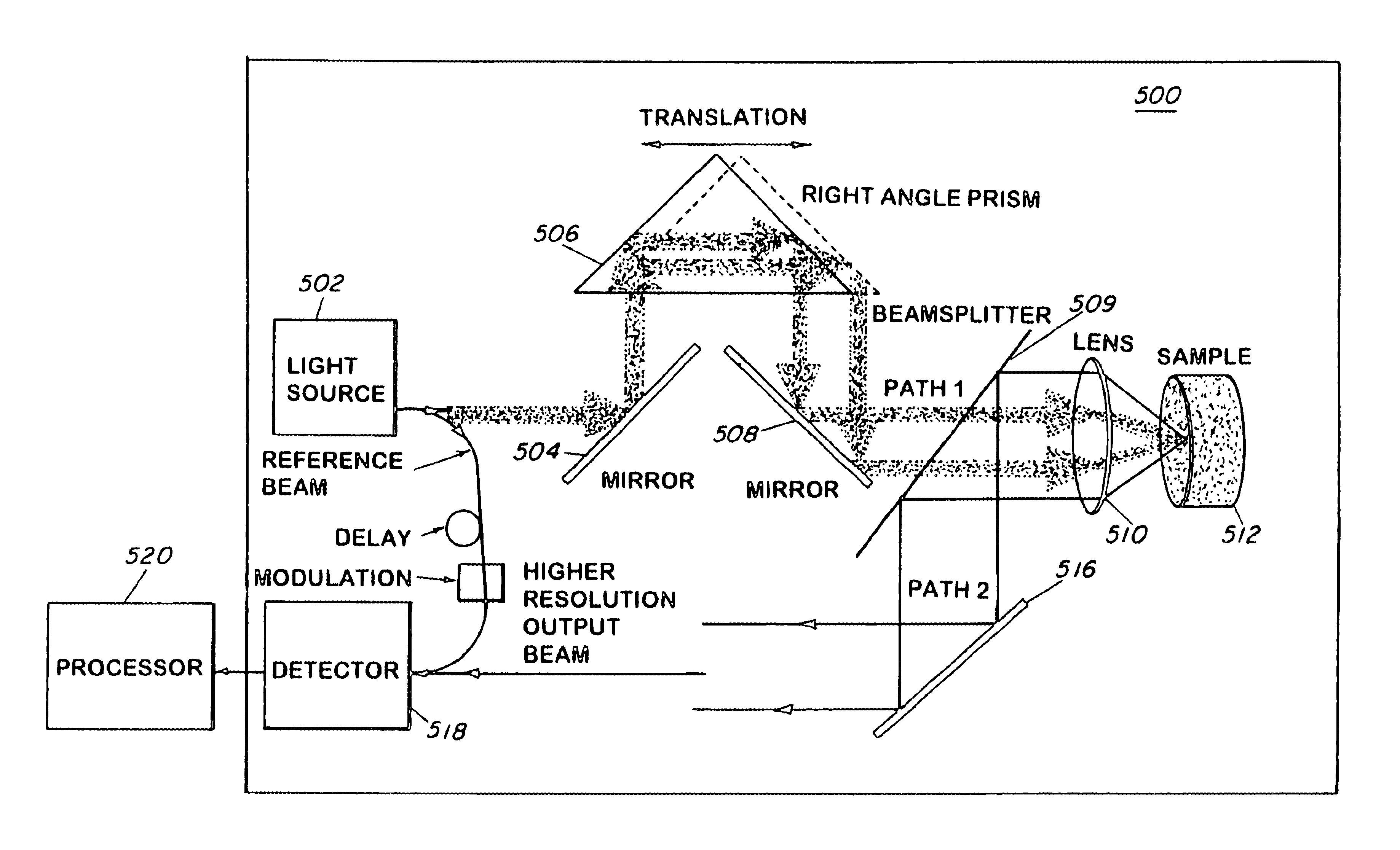
FIG. 5 is a schematic of a low-coherence fiber interferometer based system for detecting subsurface defects in a sample object in accordance with a first example embodiment of the present invention. Specifically, apparatus 500 is shown to include a low coherence light source 502 emitting an output beam that is split into an input signal beam and a reference beam. The input signal beam is reflected via a mirror 504 and a mirror 508. The incident light beam is then made to focus on sample 512 via lens 510. The angle of incidence of incident light beam that is made to focus on the sample 512 is changed by translating the input signal beam using a right angle prism 506 in front of the lens 510. Translation of the prism 506 along its hypotenuse translates the input signal beam while maintaining a constant optical path length of the beam.

Light scattered from the sample 512 is reflected back in the incidence direction and completely repeats the path of the incident beam to be detected by d...


PUM

PropertyMeasurementUnit
depthaaaaaaaaaa
scan sizeaaaaaaaaaa
optical coherence tomographyaaaaaaaaaa

Abstract

A method and apparatus for reducing speckle due to MSL, without any loss of resolution, by averaging over different angles of the incident light at low input resolution, while collecting the backscattered light at a full resolution of a lens is described. The present invention allows discrimination against the speckle due to coherent MSL.

Description

BACKGROUND OF THE INVENTION1. Field of the InventionThis invention relates to optical coherence tomography. More particularly, it relates to a method and apparatus for improving optical coherence tomography devices used for detecting scattered optical radiation from internal structures in scattering media by reducing speckle due to multiply scattered light and without any loss of resolution.2. Description of Related ArtOptical coherence tomography (OCT) is useful for imaging through highly scattering media. OCT allows for non-invasive, non-destructive cross-sectional optical imaging of scattering media with high spatial resolution and high sensitivity. OCT is related to white light interferomtery (WLI) and low coherence domain reflectometry (LCDR). WLI is used for one or two-dimensional profiling of surfaces. LCDR is used for one-dimensional depth probing of materials. OCT is used for two or three-dimensional internal probing of both scattering and non-scattering materials. The subj...

Claims


Application Information

Patent Timeline
Patent Type & Authority Patents(United States)
IPC IPC(8): G01N21/47
CPCG01N21/4795
Inventor BASHKANSKY, MARKREINTJES, JOHN F
Owner THE UNITED STATES OF AMERICA AS REPRESENTED BY THE SECRETARY OF THE NAVY
Learn More