
Electron gun for a multiple beam klystron using magnetic focusing with a magnetic field corrector

a technology of magnetic focusing and electron gun, which is applied in the direction of klystrons, electric discharge tubes, electrical apparatus, etc., can solve the problems of limiting the frequency at which this technique can be applied, limiting the average and peak power capability of the device, and not providing confined flow focusing on the device described by symons, etc., to achieve the effect of increasing the gain, bandwidth and efficacy of the devi

Inactive Publication Date: 2005-01-25
CALABAZAS CREEK RES
View PDF9 Cites 28 Cited by
  • Summary
  • Abstract
  • Description
  • Claims
  • Application Information

AI Technical Summary

Benefits of technology

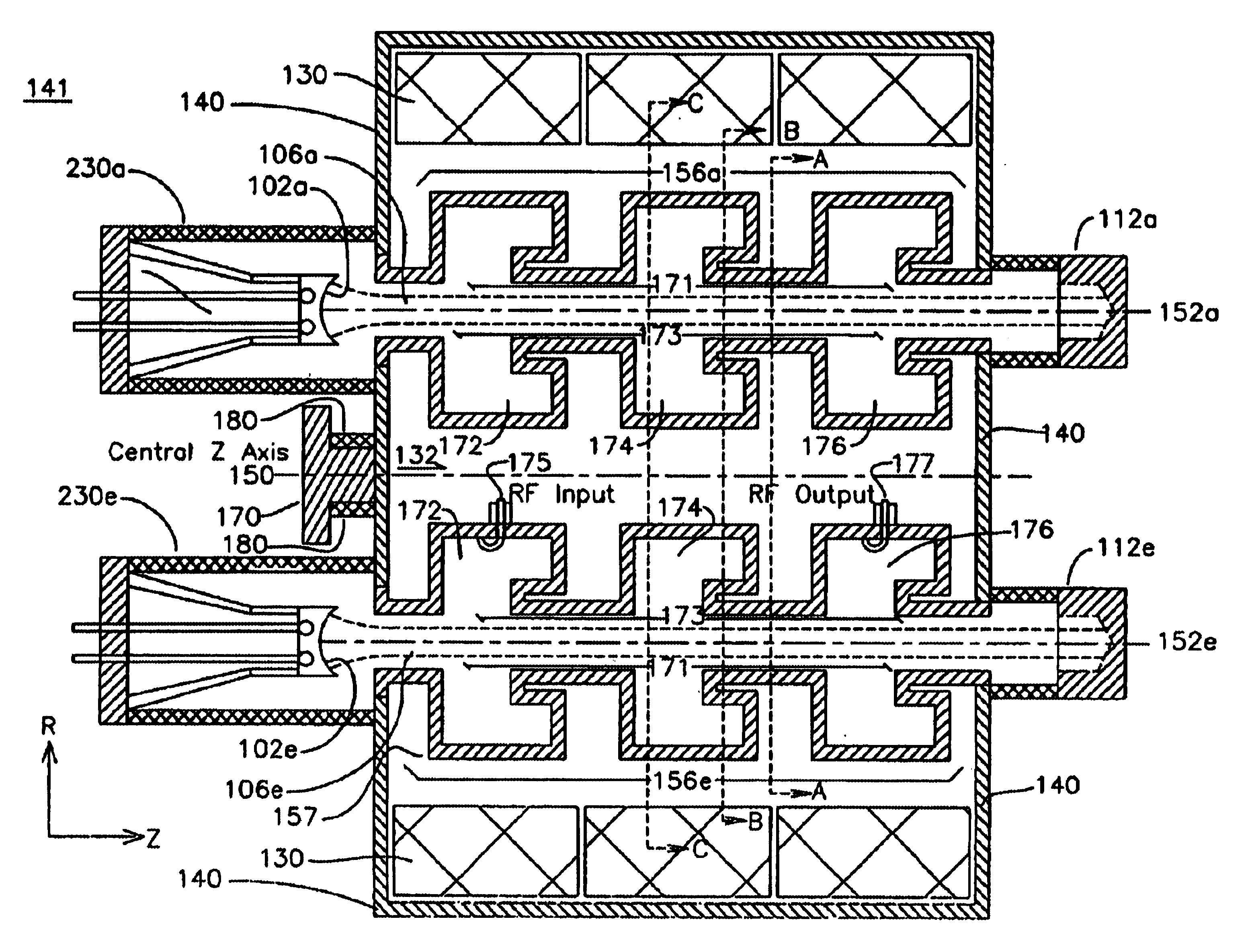
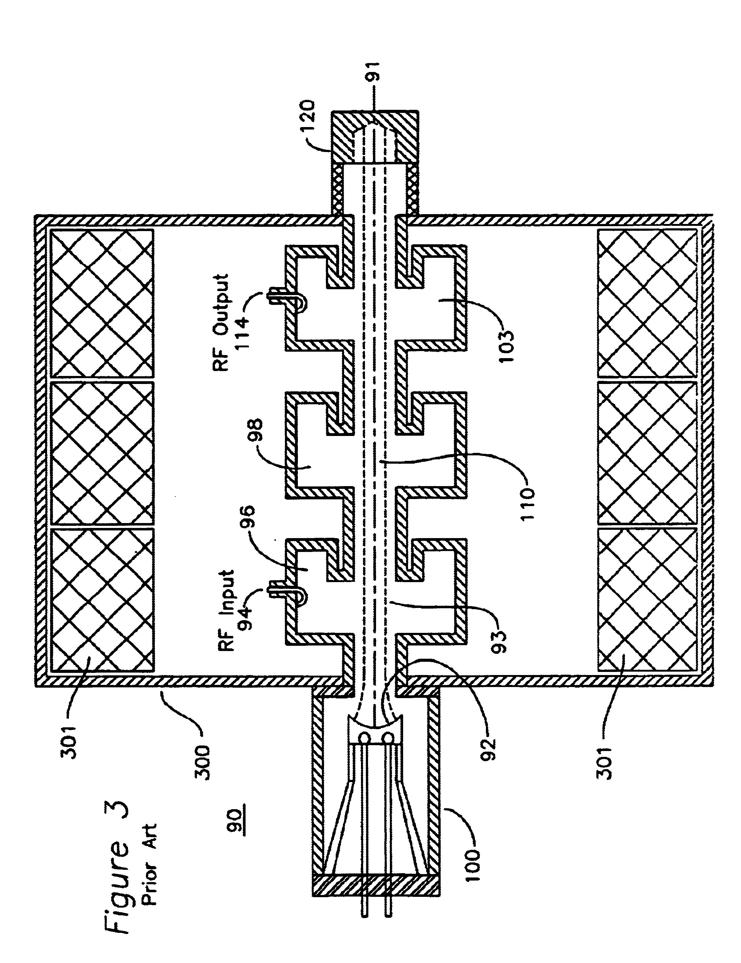
In one embodiment of the invention, the beam tunnels for each electron beam include drift tubes having a first resonant cavity defined by a first gap provided in the plurality of drift tubes, and a second resonant cavity defined by a second gap provided in the plurality of drift tubes. An electromagnetic signal is coupled into an RF input port to the first resonant cavity, which velocity modulates the beamlets traveling in the plurality of drift tubes. The velocity modulated beamlets then induce an electromagnetic signal into the second resonant cavity, which may then be extracted from the device RF output port as a high power microwave signal. Other resonant cavities may also be applied between the first and final resonant cavity to increase the gain, bandwidth and efficieny of the device. A collector is disposed at respective ends of the plurality of drift tubes, which collects the remaining energy of the beamlets after passing across the various cavities. A magnetic field oriented coaxially to the beam tunnel is furnished to provide confined flow of the electron beam.

Problems solved by technology

The device described by Symons does not provide for confined flow focusing, as it can be seen that no magnetic focusing field is applied, and beam focusing is performed entirely by electrostatic potentials applied to the many grids.
Consequently, the beam will not be fully confined in the presence of space charge bunching, limiting the average and peak power capability of the device.
Further, the device described by Symons applies only to fundamental mode cavities, which limits the frequency at which this technique can be applied.
Consequently, the number of beams that can propagate through a fundamental mode cavity becomes limited by mechanical and thermal constraints.
A disadvantage of this structure is that the annular beam tunnels can allow transmission of higher order cavity modes back toward the electron gun.
These modes can lead to undesired bunching of the electron beam and prevent operation at the desired frequency and power.
Consequently, the gain of this device is limited to less than 25, and the output power level is limited to a few megawatts.
Since these magnets can not tolerate high temperatures, they must be applied after construction of the vacuum envelope of the rf device.

Method used


Image

  • Electron gun for a multiple beam klystron using magnetic focusing with a magnetic field corrector
  • Electron gun for a multiple beam klystron using magnetic focusing with a magnetic field corrector
  • Electron gun for a multiple beam klystron using magnetic focusing with a magnetic field corrector

Examples


Embodiment Construction

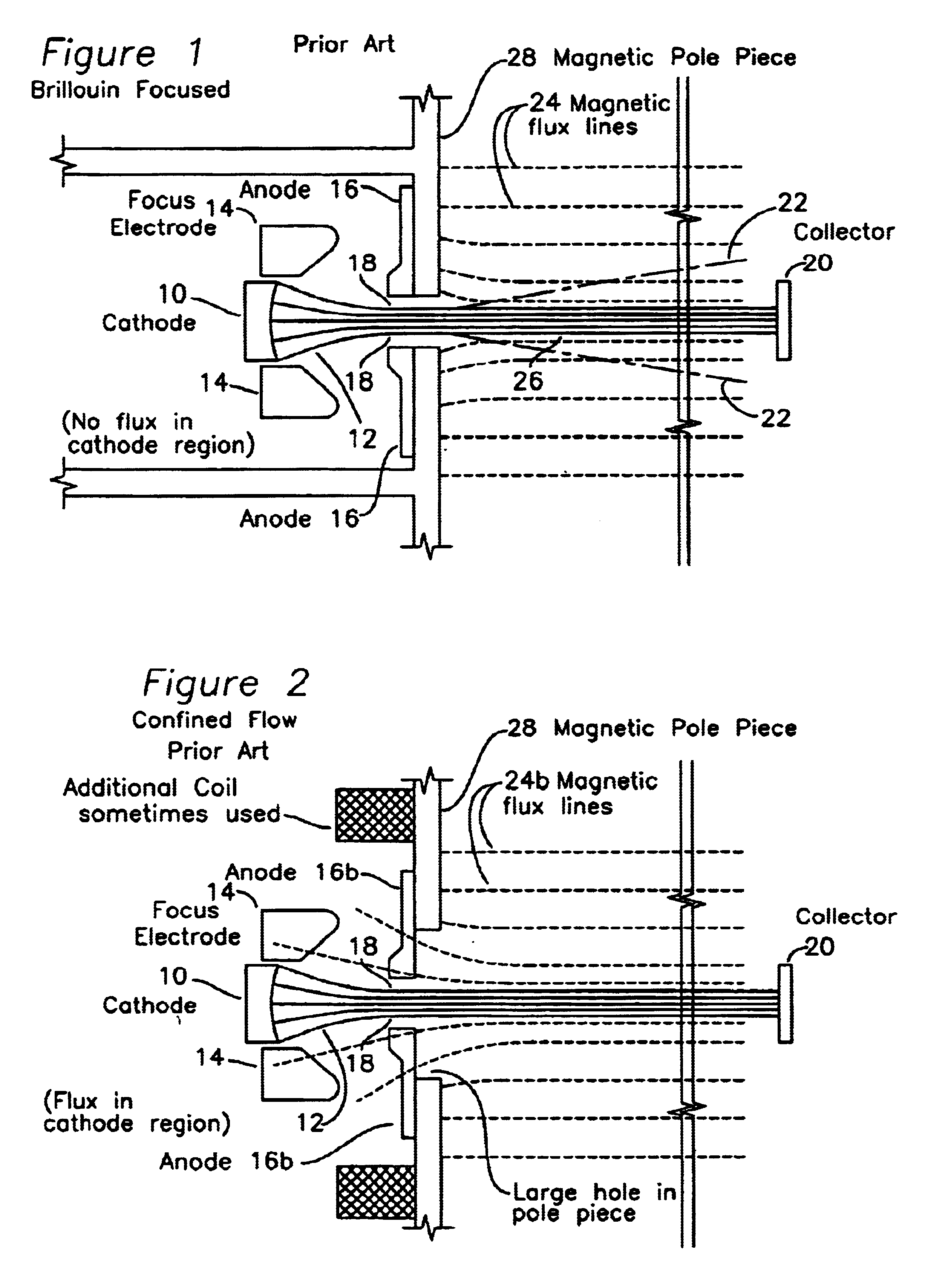
FIG. 1 shows a prior art Brillouin focused electron gun. A cathode 10 provides a flow of electrons 12 past an anode 16 at a positive voltage with respect to the cathode to a distant collector 20. In a Pierce gun, focus electrode 14 shapes the electron beam to a region of minimum beam diameter 18. Without a magnetic field, the self-charge of the electron beam causes beam spreading due to the space charge effect as shown in the trajectory 22. In Brillouin focusing, a magnetic field 24 is added which is coaxial to the beam 12, and of sufficient magnitude to cancel the space charge spreading, which results in the constant width beam 26, as shown. This magnetic field 24 may be provided through the introduction of electromagnetic coils or permanent magnet material and magnetic pole piece 28.

FIG. 2 shows a prior art confined flow electron gun. As before, a Pierce gun comprising cathode 10 and focus electrode 14 produces an electron beam 12, which converges to a region of minimum diameter 1...


PUM


Abstract

An RF device comprising a plurality of drift tubes, each drift tube having a plurality of gaps defining resonant cavities, is immersed in an axial magnetic field. RF energy is introduced at an input RF port at one of these resonant cavities and collected at an output RF port at a different RF cavity. A plurality of electron beams passes through these drift tubes, and each electron beam has an individual magnetic shaping applied which enables confined beam transport through the drift tubes.

Description

FIELD OF THE INVENTIONThe present invention relates to linear beam electron devices, and more particularly, to an electron gun that provides multiple convergent electron beamlets suitable for use in a multiple beam klystron using confined flow magnetic focusing.BACKGROUND OF THE INVENTIONLinear beam electron devices are used in sophisticated communication and radar systems that require amplification of a radio frequency (RF) or microwave electromagnetic signal. A conventional klystron is an example of a linear beam electron device used as a microwave amplifier. In a klystron, an electron beam is formed by applying a voltage potential between a cathode emitting electrons and an anode accelerating these emitted electrons such that the cathode is at a more negative voltage with respect to the anode. The electrons originating at the cathode of an electron gun are thereafter caused to propagate through a drift tube, also called a beam tunnel, comprising an equipotential surface, thereby ...

Claims


Application Information

Patent Timeline
IPC IPC(8): H01J23/087H01J23/02H01J25/00H01J25/02H01J25/10H01J23/065
CPCH01J25/10H01J23/065
Inventor IVES, R. LAWRENCEMIRAM, GEORGE
Owner CALABAZAS CREEK RES
Learn More