Dynamoelectric machine having windings that differ in wire gauge and number of winding turns

a technology of dynamoelectric machines and windings, which is applied in the direction of windings, rotating magnets, mechanical energy handling, etc., can solve the problems of unacceptable efficiency of motors and prior art motors over the entire range of motor operating speeds, limited operating range, and low efficiency of motors. achieve the effect of wide operating speed range, improved efficiency, and high degree of precision controllability

Inactive Publication Date: 2005-01-25
HANON SYST EFP BAD HOMBURG GMBH
View PDF9 Cites 19 Cited by
  • Summary
  • Abstract
  • Description
  • Claims
  • Application Information

AI Technical Summary

Benefits of technology

The above-identified copending related U.S. patent application of Maslov et al., Ser. No. 09 / 826,423, identifies and addresses the need for an improved motor amenable to simplified manufacture and capable of efficient and flexible operating characteristics. In a vehicle drive environment, it is highly desirable to attain smooth operation over a wide speed range, while maintaining a high torque output capability at minimum power consumption. The copending related U.S. application incorporates electromagnet poles as isolated magnetically permeable structures configured as segments in an annular ring, relatively thin in the radial direction, to provide advantageous effects. With this arrangement, flux can be concentrated, with virtually no loss or deleterious transformer interference effects in the electromagnet cores, as compared with prior art embodiments.
. With this arrangement, flux can be concentrated, with virtually no loss or deleterious transformer interference effects in the electromagnet cores, as compared with prior art embodiments.
The Maslov et al. applications recognize that isolation of the electromagnet segments permits individual concentration of flux in each magnetic core segment, with virtually no flux loss or deleterious transformer interference effects from flux interaction with other core segments. Operational advantages can be gained by configuring a single pole pair as an autonomous electromagnet. Magnetic path isolation of the individual pole pair from other pole pairs eliminates a flux transformer effect on an adjacent group when the energization of the pole pair windings is switched.
The above-identified copending U.S. patent application Ser. No. 10 / 173,610 is directed to a control system for a multiphase motor having these structural features. A control strategy is described that compensates for individual phase circuit characteristics and offers a higher degree of precision controllability since each phase control loop is closely matched with its corresponding winding and structure. Control parameters are specifically matched with characteristics of each respective stator phase. Successive switched energization of each phase winding is governed by a controller that generates signals in accordance with the parameters associated with the stator phase component for the phase winding energized.
While the motors described in the above-identified applications provide operational advantages, these motors and prior art motors do not exhibit uniformly high efficiency at all speeds of a wide operating speed range, even with non-variable loads. For a fixed motor topology, the available magnetomotive force (MMF) is dependent upon the number of winding turns and energization current. The term “motor topology” is used herein to refer to physical motor characteristics, such as dimensions and magnetic properties of stator cores, the number of coils of stator windings and wire diameter (gauge), etc. The available magnetomotive force dictates a variable, generally inverse, relationship between torque and speed over an operating range. An applied energization current may drive the motor to a nominal operating speed. As the motor accelerates toward that speed, the torque decreases, the current drawn to drive the motor decreases accordingly, and thus efficiency increases to a maximum level. As speed increases beyond the level of peak efficiency, additional driving current is required, thereby sacrificing efficiency thereafter. Thus, efficiency is variable throughout the speed range and approaches a peak at a speed well below maximum speed.
Motors with different topologies obtain peak efficiencies at different speeds, as illustrated in FIG. 1. This figure is a plot of motor efficiency versus operating speed over a wide speed range for motors having different topologies. The topologies represented in this figure differ solely in the number of stator winding turns. Each efficiency curve approaches a peak value as the speed increases from zero to a particular speed and then decreases toward zero efficiency. Curve A, which represents the motor with the greatest number of winding turns, exhibits the steepest slope to reach peak efficiency at the earliest speed V2. Beyond this speed, however, the curve exhibits a similarly steep negative slope. Thus, the operating range for this motor is limited. The speed range window at which this motor operates at or above an acceptable level of efficiency, indicated as X% in FIG. 1, is relatively narrow.

Problems solved by technology

The progressive improvement of electronic systems, such as microcontroller and microprocessor based applications for the control of motors, as well as the availability of improved portable power sources, has made the development of efficient electric motor drives for vehicles, as a viable alternative to combustion engines, a compelling challenge.
While the motors described in the above-identified applications provide operational advantages, these motors and prior art motors do not exhibit uniformly high efficiency at all speeds of a wide operating speed range, even with non-variable loads.
Thus, the operating range for this motor is limited.
Each motor has peak efficiency at a different motor operating speed, and none has acceptable efficiency over the entire range of motor operating speeds.
Structural constraints in particular motor configurations may limit the number of taps, and thus coil sets, that are available from individual stator windings.

Method used


Image

  • Dynamoelectric machine having windings that differ in wire gauge and number of winding turns
  • Dynamoelectric machine having windings that differ in wire gauge and number of winding turns
  • Dynamoelectric machine having windings that differ in wire gauge and number of winding turns

Examples


Embodiment Construction

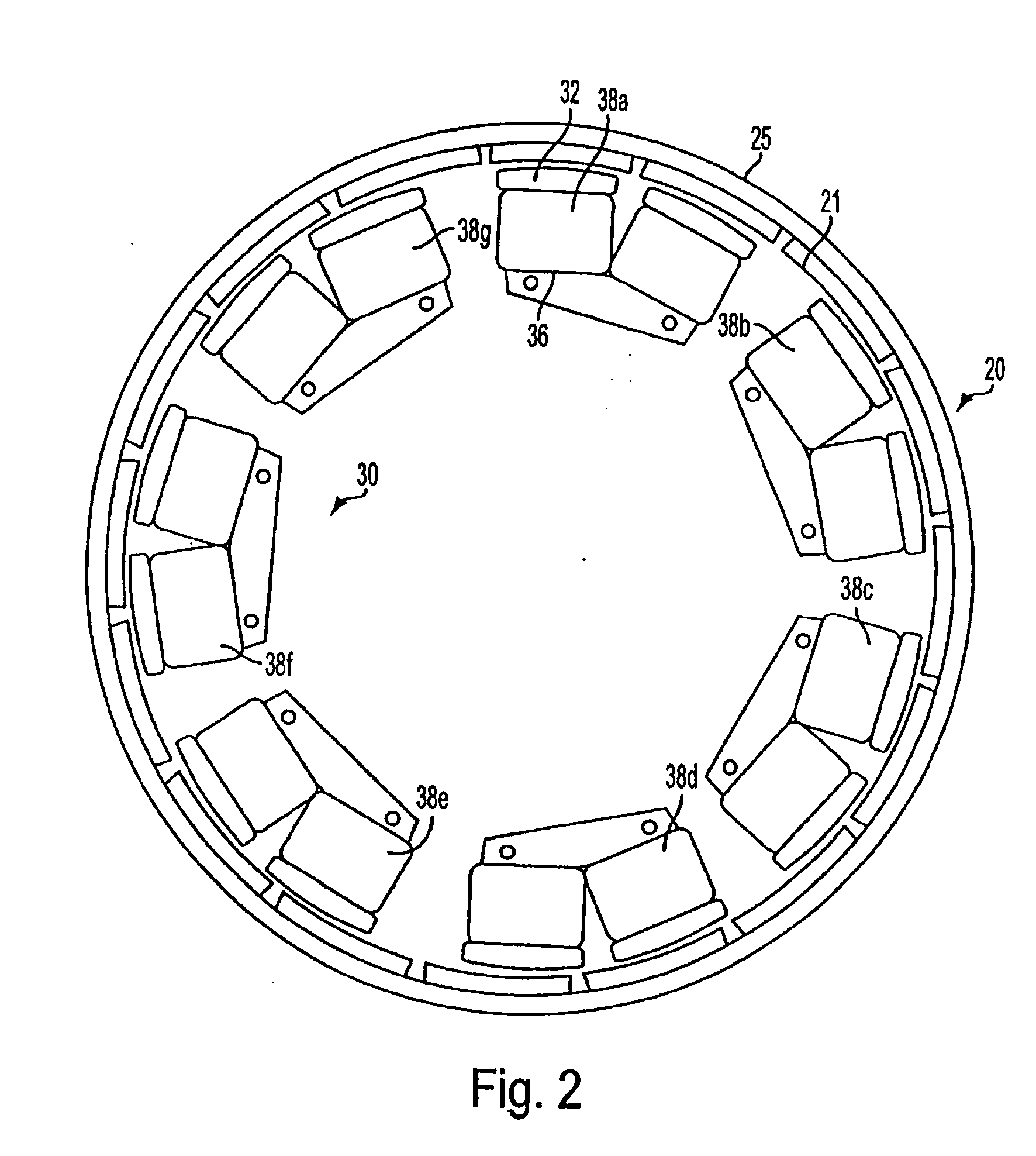
FIG. 2 is an exemplary configuration of rotor and stator elements that may be employed in the present invention. Reference is made to the above identified copending Maslov et al. application Ser. No. 09 / 826,422 for a more detail description of the motor exemplified herein. Rotor member 20 is an annular ring structure having permanent magnets 21 spaced from each other and substantially evenly distributed along cylindrical back plate 25. The permanent magnets are rotor poles that alternate in magnetic polarity along the inner periphery of the annular ring. The rotor surrounds a stator member 30, the rotor and stator members being separated by an annular radial air gap. Stator 30 comprises a plurality of electromagnet core segments of uniform construction that are evenly distributed along the air gap.

The stator comprises seven core segments, each core segment formed in a generally unshaped magnetic structure 36 with two poles having surfaces 32 facing the air gap. The legs of the pole ...


PUM


Abstract

A multiphase motor comprises a plurality of ferromagnetic stator core segments, the core segments being substantially uniformly spaced around an axis of rotation and isolated from direct contact with each other. Each core segment forms at least one pair of poles having coils wound thereon to form a phase winding. Each stator phase winding is configured with a topology different from the topology of each of the other phase windings. Each phase winding has a different total number of coils from one or more of the other phase windings. Each phase winding comprises coils of a gauge different from the coil gauge of one or more of the other phase windings. Preferably, all of the phase windings have substantially the same total coil mass.

Description

FIELD OF THE INVENTIONThe present invention relates to dynamoelectric machine structure, more particularly to a stator structure comprising a plurality of segments with respective windings of different total numbers of winding coils and wire gauges.BACKGROUNDThe progressive improvement of electronic systems, such as microcontroller and microprocessor based applications for the control of motors, as well as the availability of improved portable power sources, has made the development of efficient electric motor drives for vehicles, as a viable alternative to combustion engines, a compelling challenge. Electronically controlled pulsed energization of windings of motors offers the prospect of more flexible management of motor characteristics. By control of pulse width, duty cycle, and switched application of a battery source to appropriate stator windings, functional versatility that is virtually indistinguishable from alternating current synchronous motor operation can be achieved.The...

Claims


Application Information

Patent Timeline
Patent Type & Authority Patents(United States)
IPC IPC(8): H02K3/28H02K21/22
CPCH02K21/225H02K3/28H02K1/187H02K1/2733
Inventor GLADKOV, ALEXANDER A.
Owner HANON SYST EFP BAD HOMBURG GMBH
Why Eureka
Try Eureka