
Methods and apparatus for power control in a scalable array of processor elements

a technology of processor elements and power control, applied in the direction of program control, liquid/fluent solid measurement, instruments, etc., can solve the problems of reducing power, reducing power, and reducing embedded ram at the expense of expanding external ram, so as to reduce power, reduce power, and reduce power

Inactive Publication Date: 2005-01-18
ALTERA CORP
View PDF4 Cites 20 Cited by
  • Summary
  • Abstract
  • Description
  • Claims
  • Application Information

AI Technical Summary

Benefits of technology

In one aspect of the present invention, the ManArray configurable register file is appropriately controlled to reduce power in each PE and in the SP. In addition, PE masking is used to reduce power to those PEs that are not active. In another aspect, power can be reduced in conditionally executing multi-cycle operations where execution cycles are curtailed as soon as the execution conditions have been determined. Also, power can be reduced in a VLIW execution since there is no need to read the same VIM location as the previous execute (XV) VLIW instruction that used the same VIM address. In a further aspect, power can be reduced in a ManArray processor that supports register file indexing (RFI) since there is no need to read the same VIM location on each XV received that is using RFI.

Problems solved by technology

Reducing embedded RAM at the expense of expanding external RAM, however, is not necessarily a good tradeoff.
When functions are not used during different time periods, gating the clock off to the unused logic for those periods reduces the switching of signals thereby reducing power.
Low power approaches many times can conflict with high performance requirements.
This conflict occurs typically because the primary approach to achieving high performance is through high clock rates.
If the complex instruction was to be implemented in a high clock rate design, then the complex function would be broken up into multiple pipeline stages which directly affects the complexity of the design and of the programming model.
Thus, the increased hardware complexity and less efficient programming utilization can mask out any power improvements obtained from the higher clock rates.

Method used


Image

  • Methods and apparatus for power control in a scalable array of processor elements
  • Methods and apparatus for power control in a scalable array of processor elements
  • Methods and apparatus for power control in a scalable array of processor elements

Examples


Embodiment Construction

Further details of a presently preferred ManArray core, architecture, and instructions for use in conjunction with the present invention are found in U.S. patent application Ser. No. 08 / 885,310 filed Jun. 30, 1997, now U.S. Pat. No. 6,023,753,U.S. patent application Ser. No. 08 / 949,122 filed Oct. 10, 1997, now U.S. Pat. No. 6,167,502,U.S. patent application Ser. No. 09 / 169,255 filed Oct. 9, 1998, now U.S. Pat. No. 6,343,356,U.S. patent application Ser. No. 09 / 169,256 filed Oct. 9, 1998, now U.S. Pat. No. 6,167,501,U.S. patent application Ser. Na. 09 / 169,072 filed Oct. 9, 1998, now U.S. Pat. No. 6,219,776,U.S. patent application Ser. No. 09 / 187,539 filed Nov. 6, 1998, now U.S. Pat. No. 6,151,668,U.S. patent application Ser. No. 09 / 205,558 filed Dec. 4, 1998, now U.S. Pat. No. 6,173,389,U.S. patent application Ser. No. 09 / 215,081 filed Dec. 18, 1998, now U.S. Pat. No. 6,101,592,U.S. patent application Ser. No. 09 / 228,374 filed Jan. 12, 1999, now U.S. Pat. No. 6,216,223,U.S. patent app...


PUM


Abstract

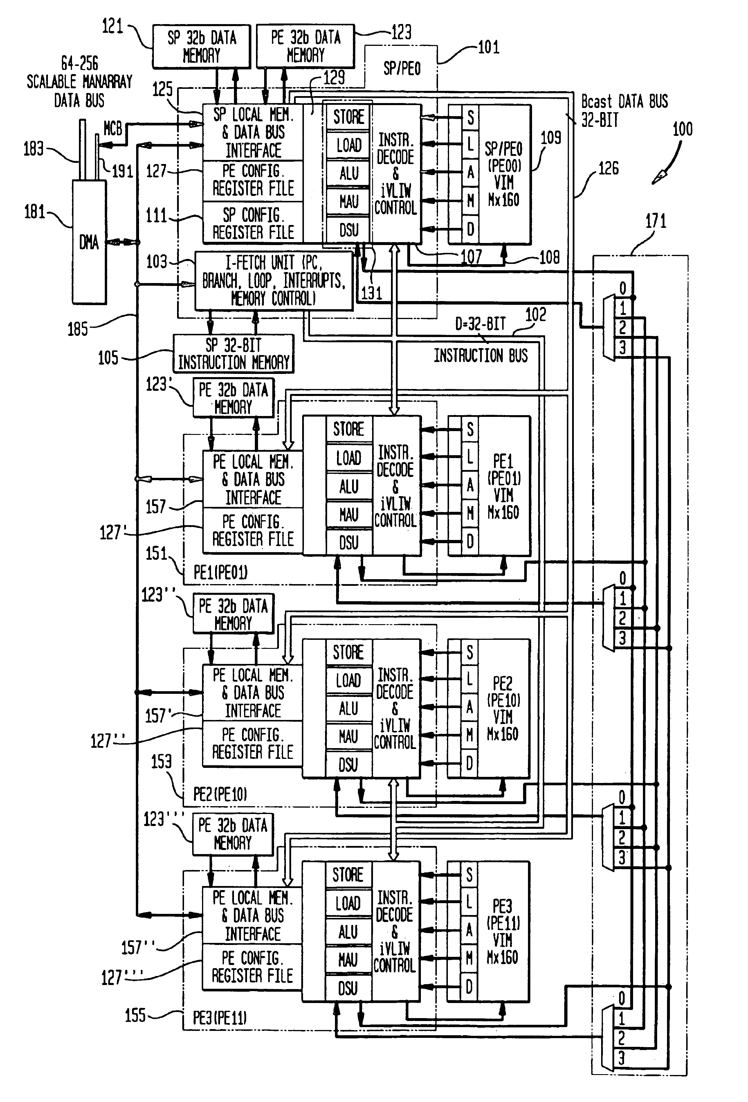
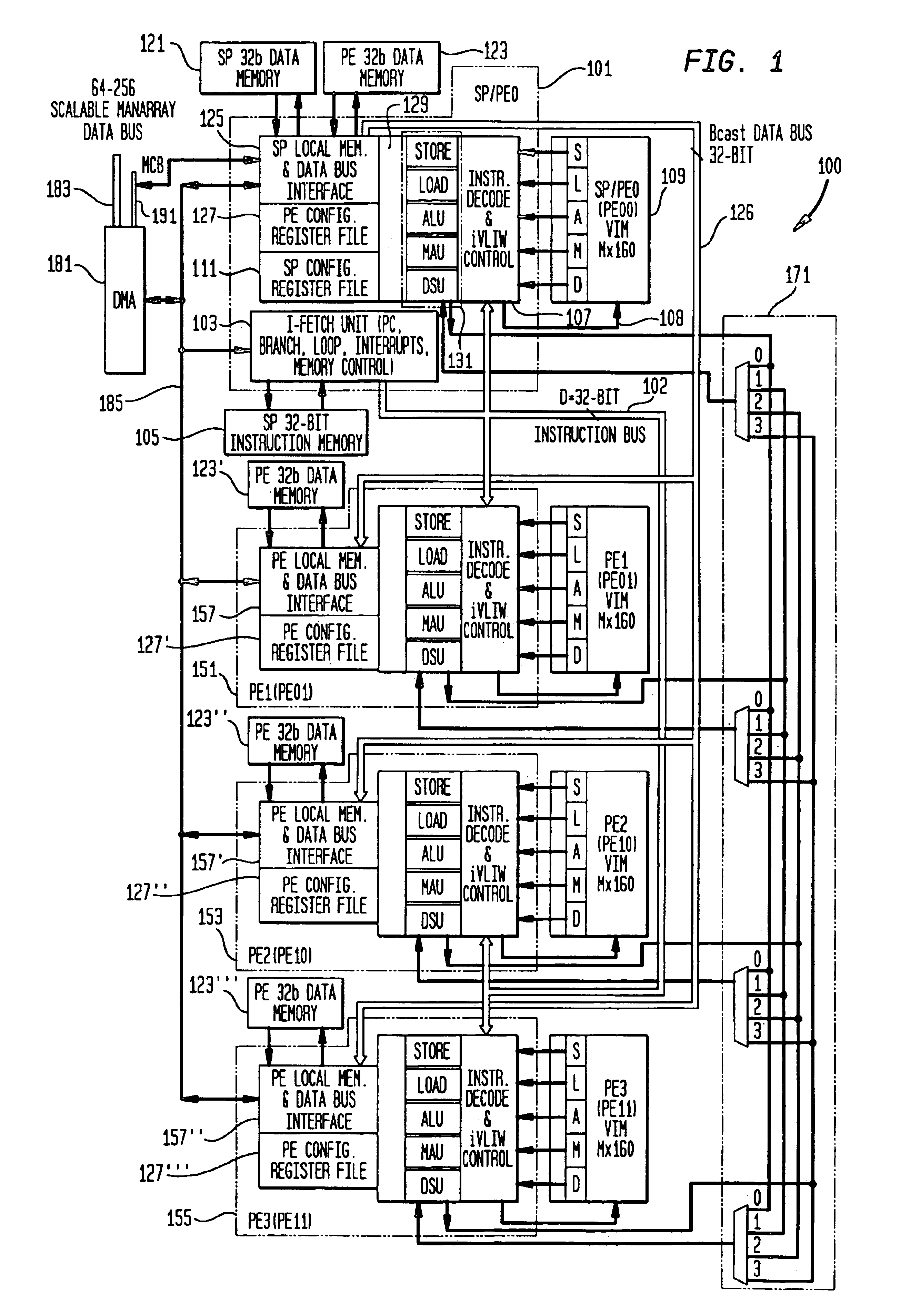
Low power architecture features and techniques are provided in a scalable array indirect VLIW processor. These features and techniques include power control of a reconfigurable register file, conditional power control of multi-cycle operations and indirect VLIW utilization, and power control of VLIW-based vector processing using the ManArray register file indexing mechanism. These techniques are applicable to all processing elements (PEs) and the array controller sequence processor (SP) to provide substantial power savings.

Description

FIELD OF THE INVENTIONThe present invention relates generally to improved techniques for power control in a scalable pipelined array processor. More particularly, the present invention addresses, among its many aspects, advantageous techniques for power control including processing elements with power control of a reconfigurable register file, conditional power control of multi-cycle operations and indirect VLIW utilizations, and power control of VLIW-based vector processing using the ManArray register file indexing mechanism.BACKGROUND OF THE INVENTIONProcessors designed to be embedded in system on a chip type products are not only required to have high performance but to provide this performance with low power consumption and small area. A low power design is achieved through architecture, micro-architecture design, implementation physical design, process, and software control innovations. A low power processor architecture defines the instruction set and programming model which f...

Claims


Application Information

Patent Timeline
IPC IPC(8): G06F1/32G06F9/38G06F9/30
CPCG06F1/3203G06F9/30036G06F9/3891G06F9/3853G06F9/3885G06F9/30101G06F9/30038
Inventor MARCHAND, PATRICK R.PECHANEK, GERALD G.WOLFF, EDWARD A.
Owner ALTERA CORP
Learn More