
Heat-sensitive odor-emitting component

a technology of odor-emitting components and heat-sensitive components, which is applied in the direction of heat measurement, fire alarms, instruments, etc., can solve the problems of high cost of thermal sensors, inability to accurately grasp overheating phenomena in equipment, and extreme increase in equipment temperature, etc., to achieve excellent long-term stability and high heat sensitivity

Inactive Publication Date: 2005-01-18
HITACHI CABLE
View PDF12 Cites 17 Cited by
  • Summary
  • Abstract
  • Description
  • Claims
  • Application Information

AI Technical Summary

Benefits of technology

The invention has been made with a view to effectively solving the above problems of the prior art, and it is an object of the invention to provide a novel heat-sensitive odor-emitting component which possesses high sensitivity to heat and, at the same time, possesses excellent long-term stability.
It is another object of the invention to provide a novel heat-sensitive odor-emitting component which possesses high sensitivity to heat and excellent long-term stability and is also highly stable and reliable for shortcircuiting accidents.
It is a further object of the invention to provide a novel heat-sensitive odor-emitting component which is less likely to cause erroneous working and can surely notify of the occurrence of an abnormal overheating phenomenon.
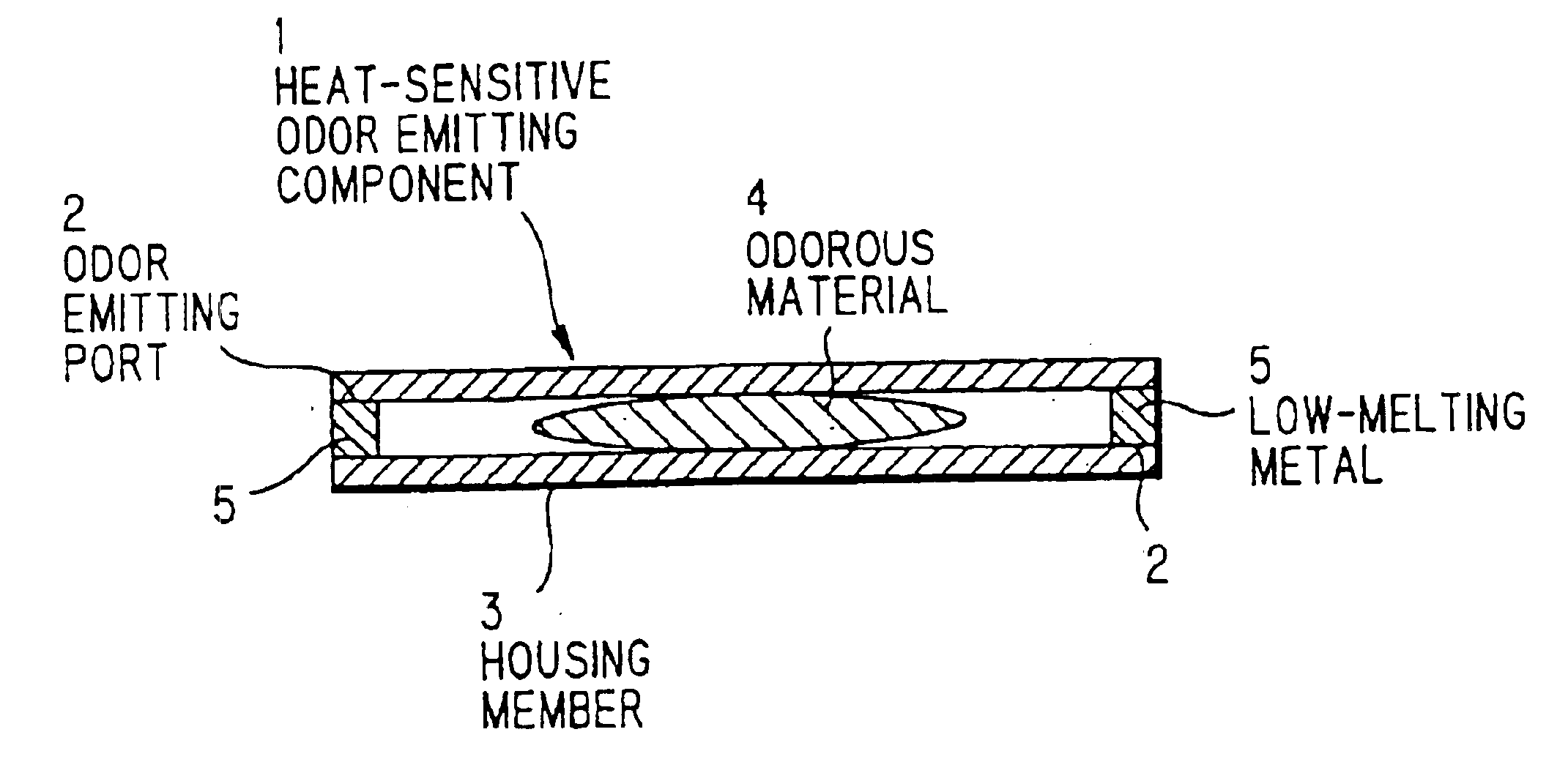
The housing member is formed of a material composed mainly of an inorganic material. Specifically, the housing member may be formed of a metal foil, a composite film of a metal foil stacked on a polymeric film, glass, a glass-coated polymeric film, or a metallic container. In this case, as compared with resin, the housing member formed of the above material is not deteriorated over a long period of time, and stable function can be realized, that is, erroneous working attributable, for example, to the leakage of the odorous material caused, for example, by deterioration or breakage can be avoided.
When an electrically insulting coating material is used for the formation of the electrically insulating layer, the electrically insulating layer can be easily formed on the surface of the metallic container to cover the metallic container.

Problems solved by technology

In conventional electric equipment, domestic equipment, and other equipment, for example, an increase in load, a contact failure, or leakage of electricity causes the flow of overcurrent which extremely increases the temperature of the equipment.
This method is disadvantageous in that there is a need to always monitor the color-change tape and a local overheating phenomenon within the equipment cannot be accurately grasped.
This thermal sensor is generally expensive and, in addition, a large number of thermal sensors, wiring, and alarm equipment should be mounted together.
This is not practical from the viewpoint of cost.
As a result, there is a fear that the odor-emitting material does not work even when the temperature has reached the abnormal overheating temperature region, or otherwise the odor-emitting material works before the temperature reaches the abnormal overheating temperature region.
Further, the durability and adhesion to heat generation site of the resin material are so low that long-term stability is also disadvantageously poor.
In addition, the abnormal overheating temperature at a site as an monitoring object varies depending upon the type of the equipment and the like.
In the construction of the conventional odor-emitting capsule, it is difficult to control the operating temperature with high accuracy.

Method used


Image

  • Heat-sensitive odor-emitting component
  • Heat-sensitive odor-emitting component
  • Heat-sensitive odor-emitting component

Examples


example 1

Ethanol having a boiling point of 79° C. was provided as an odorous material 33 and was placed in a metallic container 32 shown in FIG. 10. An odor-emitting port 34 was sealed with a sealing material 35 composed of a bismuth-indium alloy (weight ratio=34:66) having a melting point of 72° C. to prepare an odor-emitting component 31.

Thereafter, the odor-emitting component 31 was gradually heated. As a result, when the temperature reached about 75° C., the sealing material 35 melted down to open the odor-emitting port 34 through which ethanol was leaked. This increased the output of an electric odor detection sensor.

example 2

An odor-emitting component 31 was prepared in the same manner as in Example 1, except that n-heptane having a boiling point of 98° C. was used as the odorous material 33 and an indium-tin-bismuth alloy (weight ratio=48.2:44.4:7.4) having a melting point of 96° C. was used as the sealing material 35.

Thereafter, the odor-emitting component 31 was gradually heated. As a result, when the temperature reached about 100° C., the sealing material 35 melted down to open the odor-emitting port 34 through which n-heptane was leaked. This increased the output of an electric odor detection sensor.

example 3

An odor-emitting component 31 was prepared in the same manner as in Example 1, except that toluene having a boiling point of 111° C. was used as the odorous material 33 and a tin-indium alloy (weight ratio=48:52) having a melting point of 117° C. was used as the sealing material 35.

Thereafter, the odor-emitting component 31 was gradually heated. As a result, when the temperature reached about 120° C., the sealing material 35 melted down to open the odor-emitting port 34 through which toluene was leaked. This increased the output of an electric odor detection sensor.


PUM


Abstract

An odor-emitting port is provided in a housing member composed mainly of an inorganic material. An odorous material is contained in the housing member, and the odor-emitting port is sealed with a low-melting metal to constitute a heat-sensitive odor-emitting component. In this heat-sensitive odor-emitting component, as soon as the temperature of a heat generation site has reached a predetermined value, the low-melting metal is instantaneously melted down to open the odor-emitting port through which the odorous material contained in the housing member is immediately spread around the odor-emitting component. Therefore, the odor-emitting component is highly sensitive to temperature. Further, since the housing member is formed of an inorganic material, the long-term stability can be improved.

Description

BACKGROUND OF THE INVENTION1. Field of the InventionThe invention relates to a heat-sensitive odor-emitting component which emits an odorous material upon a rise in temperature.2. Prior ArtIn conventional electric equipment, domestic equipment, and other equipment, for example, an increase in load, a contact failure, or leakage of electricity causes the flow of overcurrent which extremely increases the temperature of the equipment. This is causative of a fault or sometimes leads to a great overheating accident such as a fire.In an example of a method for preventing the overheating accident, a color change tape, which causes a change in color upon a rise in temperature, is previously applied to a site where heat generation is expected, and whether or not the color has been changed is viewed to detect the abnormal heat generation phenomenon. This method is disadvantageous in that there is a need to always monitor the color-change tape and a local overheating phenomenon within the equi...

Claims


Application Information

Patent Timeline
IPC IPC(8): A61L9/015A61L9/03G01K11/06G01K11/02
CPCA61L9/03
Inventor ABE, TOMIYAKASUGAI, HIROSHIKAMOSHIDA, HIROSHIKASHIWAZAKI, SHIGERU
Owner HITACHI CABLE
Learn More