
Protective face shield

a protective mask and face technology, applied in the field of face protection, can solve the problems of irritating skin and eyes, unwanted side effects of treatment, and irritation of the face, so as to improve the protective qualities of the mask, facilitate breathing and talking, and improve the seal between the user's face and the mask

Inactive Publication Date: 2005-01-18
OSTROV HOLLY +1
View PDF17 Cites 4 Cited by
  • Summary
  • Abstract
  • Description
  • Claims
  • Application Information

AI Technical Summary

Benefits of technology

In a preferred embodiment of the present invention, a protective face shield includes a mask portion and a handle portion. The mask portion has an exterior surface and an interior surface. The interior surface defines a cavity adapted to accept a substantial portion of a users face. The mask portion may include a ventilation structure to facilitate breathing and talking by the user. The ventilation structure may include a plurality of holes of any shape formed in the mask portion. The ventilation structure may be raised from the exterior surface of the mask portion, but does not need to be. The mask portion may also include a flange disposed about its periphery. Such a flange may render the mask more comfortable to a user during its use, and may also improve the protective qualities of the mask during use by, for example, improving the seal between a user's face and the mask.
The mask portion is readily operatively attachable to and removable from the handle portion, thereby allowing a user, such as a beauty salon technician, to easily remove a soiled or otherwise used mask portion form the handle portion and to replace on the handle portion a clean or otherwise unused mask portion. To facilitate attaching the mask portion to the handle portion, the mask portion may further include an anchoring structure, and the handle portion may be adapted for operatively accepting this anchoring structure. The anchoring structure may be in the form of a substantially planar tab extending substantially downward from the mask portion, or may be in any other form which permits the mask portion to be attached and removed readily from the handle portion, including multiple planar tabs, dowel-like structures, hooks, and velcro-type structures. In each case, the handle portion should include an appropriate structure or structures to receive or operate with the anchoring structure.
A preferred embodiment of the present invention includes a latch assembly adapted for maintaining the handle portion in a closed orientation and which may be operated to permit the handle portion to transition to an open orientation. The latch assembly may include a hook attached to one of either the front or rear handle portion. The hook may extend through an aperture in the other of the front or rear handle portion adapted for accepting the hook there through, and may abut a surface which is disposed adjacent to the aperture, thereby maintaining the handle in a closed orientation. Be pressing the hook downwardly from its normally upwardly-biased position, the hook may freely move through the aperture, thereby allowing the handle portion to transition from its closed orientation to its open orientation.

Problems solved by technology

As these treatments are applied, recipients of the treatment often experience the undesirable side effect of incidental application of the liquid, aerosol and / or powder to areas other than the hair, including incidental application to the recipient's face.
Such incidental application to the face may have the undesirable effects of: disturbing previously applied cosmetics; irritating skin and eyes; entering the recipient's mouth, where they may be ingested accidentally; and / or dirtying the user's face.
Various attempts have been made to alleviate this problem; however, none has provided a satisfactory solution.
The disclosed design includes no means for allowing fresh air to reach easily the user's mouth and nose, and does not permit any exchange of the mask portion with the handle portion.
As a result, the mask portion may become dirty, damaged and / or otherwise caked with hair care treatments.
If the hair care treatment is a hair dying product, the mask portion may become permanently discolored.
In either event, the entire face mask would need either to be cleaned or discarded if cleaning were impossible or impracticable.
The mask includes no means for providing fresh air to reach easily the user's mouth and nose, and provides no means for easily placing a new, clean mask portion onto the handle portion.
These devices both have the common shortcoming of not permitting a user to easily change mask portions when a particular mask portion becomes dirty, damaged or otherwise unusable; instead, such replacement would require disassembling and reassembling the device if such were possible at all.

Method used


Image

  • Protective face shield
  • Protective face shield
  • Protective face shield

Examples


Embodiment Construction

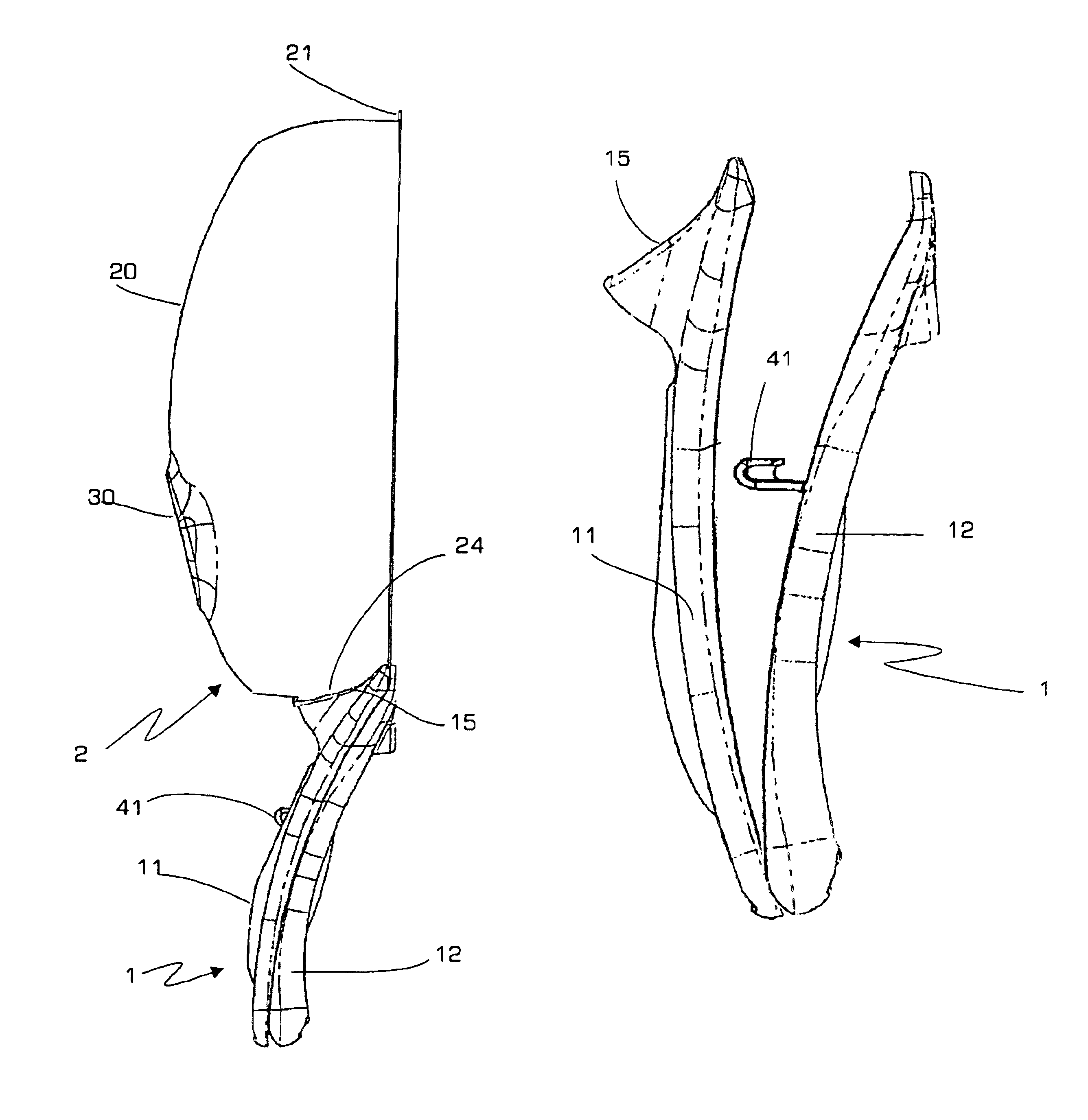
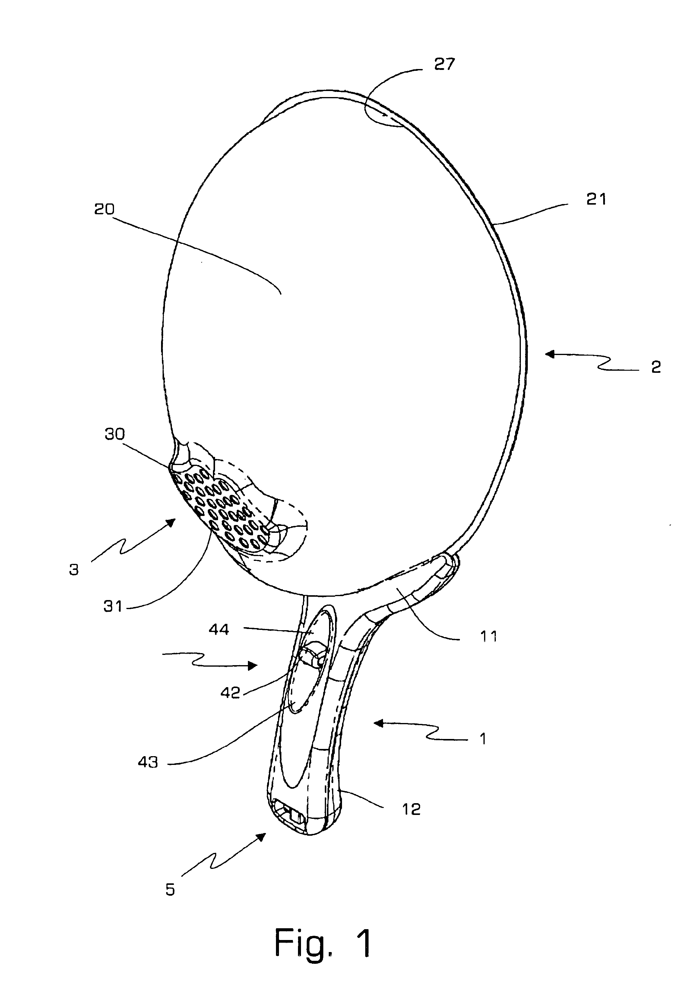
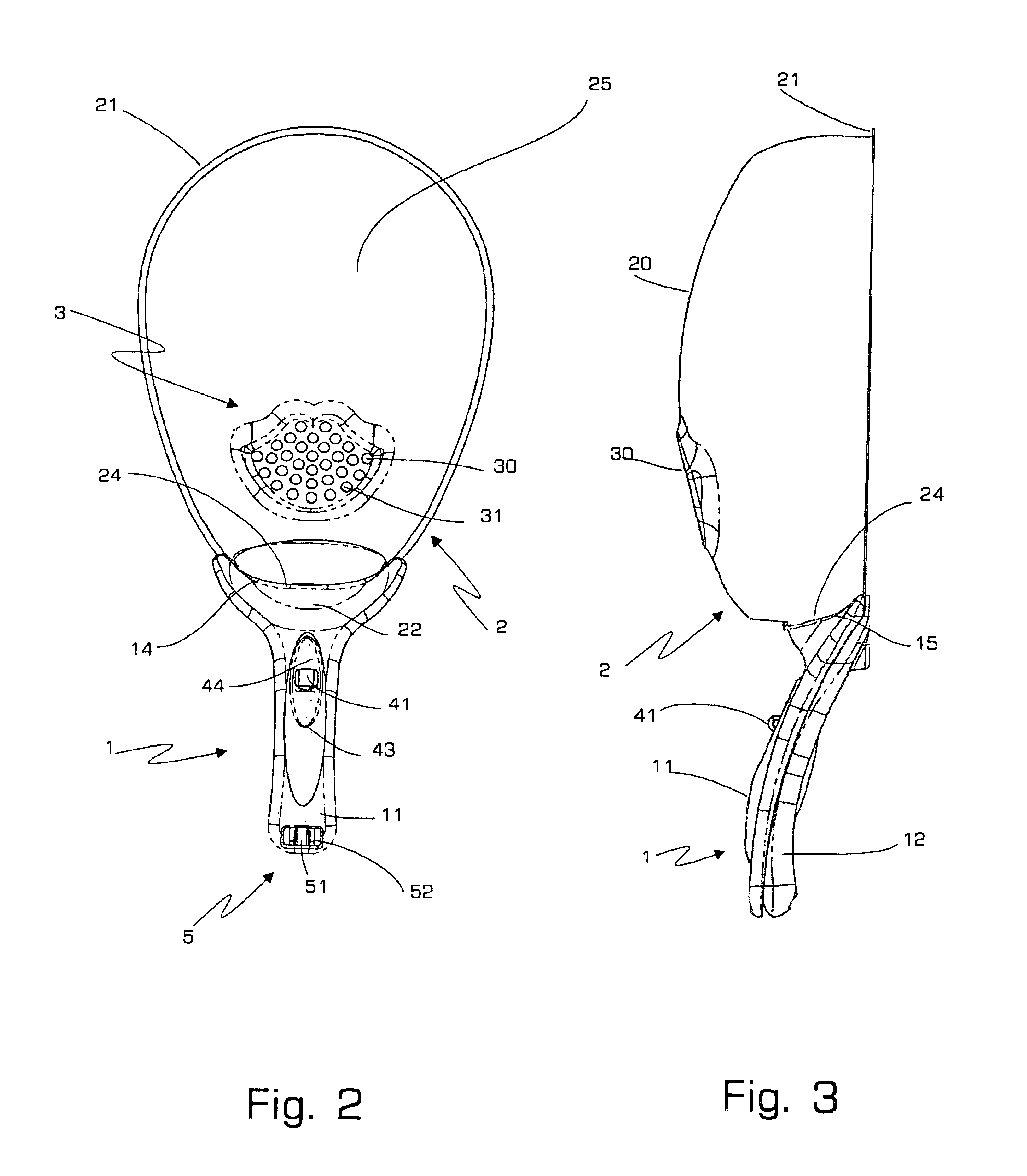
Referring now in detail to the drawings wherein like reference numerals identify similar structural features of the several embodiments of the subject invention, there is illustrated in FIG. 1 an isometric view of a preferred embodiment of the present invention. Mask portion 2 is operatively connected to handle portion 1. Mask portion 2 includes ventilation structure 3 disposed generally in the lower portion of exterior surface 20, and includes ventilation holes 31 in the form of perforations contained in raised surface 30. Flange 21 extends around the periphery of mask portion 2.

Handle portion 1 includes front portion 11 and rear portion 12 operatively connected to one another by hinge assembly 5 and maintained in closed orientation by latch assembly 4. Latch assembly 4 includes concave portion 43 formed in front handle portion 11. Concave portion 43 contains aperture 42, through which hook 41 extends. Hook 41 is permanently affixed to rear handle portion 12, preferably integrally ...


PUM


Abstract

A protective face shield comprising a mask portion and a handle portion, the mask portion having an exterior surface and an interior surface. The mask portion is readily operatively attachable to and removable from the handle portion, and the interior surface definines a cavity adapted to accept a substantial portion of a users face.

Description

BACKGROUND OF THE INVENTION1. Field of the InventionThe present invention relates generally to the field of protective coverings for the face, and more specifically to protective coverings for the face for use in connection with the application of hair treatments.2. Background of the Related ArtModem hair treatments often require the application of various liquid, aerosol, non-aerosol pumped, non-aerosol sprayed and / or powdered products to the hair. As these treatments are applied, recipients of the treatment often experience the undesirable side effect of incidental application of the liquid, aerosol and / or powder to areas other than the hair, including incidental application to the recipient's face. Such incidental application to the face may have the undesirable effects of: disturbing previously applied cosmetics; irritating skin and eyes; entering the recipient's mouth, where they may be ingested accidentally; and / or dirtying the user's face.Various attempts have been made to al...

Claims


Application Information

Patent Timeline
Patent Type & Authority Patents(United States)
IPC IPC(8): A41D13/05A41D13/11A45D44/00A45D44/12A61F9/04A61F9/06
CPCA41D13/11A61F9/06A45D44/12
Inventor OSTROV, HOLLYBRETTLER, RITA D.
Owner OSTROV HOLLY
Learn More