
Method and apparatus for monitoring superconducting magnet data

a superconducting magnet and data monitoring technology, applied in the field of medical imaging devices, can solve the problems of relatively high production and maintenance costs of cryogenic liquids, difficult maintenance of electromagnets, and loss of helium, so as to facilitate predictive maintenance, reduce maintenance costs, and reduce the effect of mri downtim

Inactive Publication Date: 2005-01-04
GE MEDICAL TECH SERVICES
View PDF3 Cites 34 Cited by
  • Summary
  • Abstract
  • Description
  • Claims
  • Application Information

AI Technical Summary

Benefits of technology

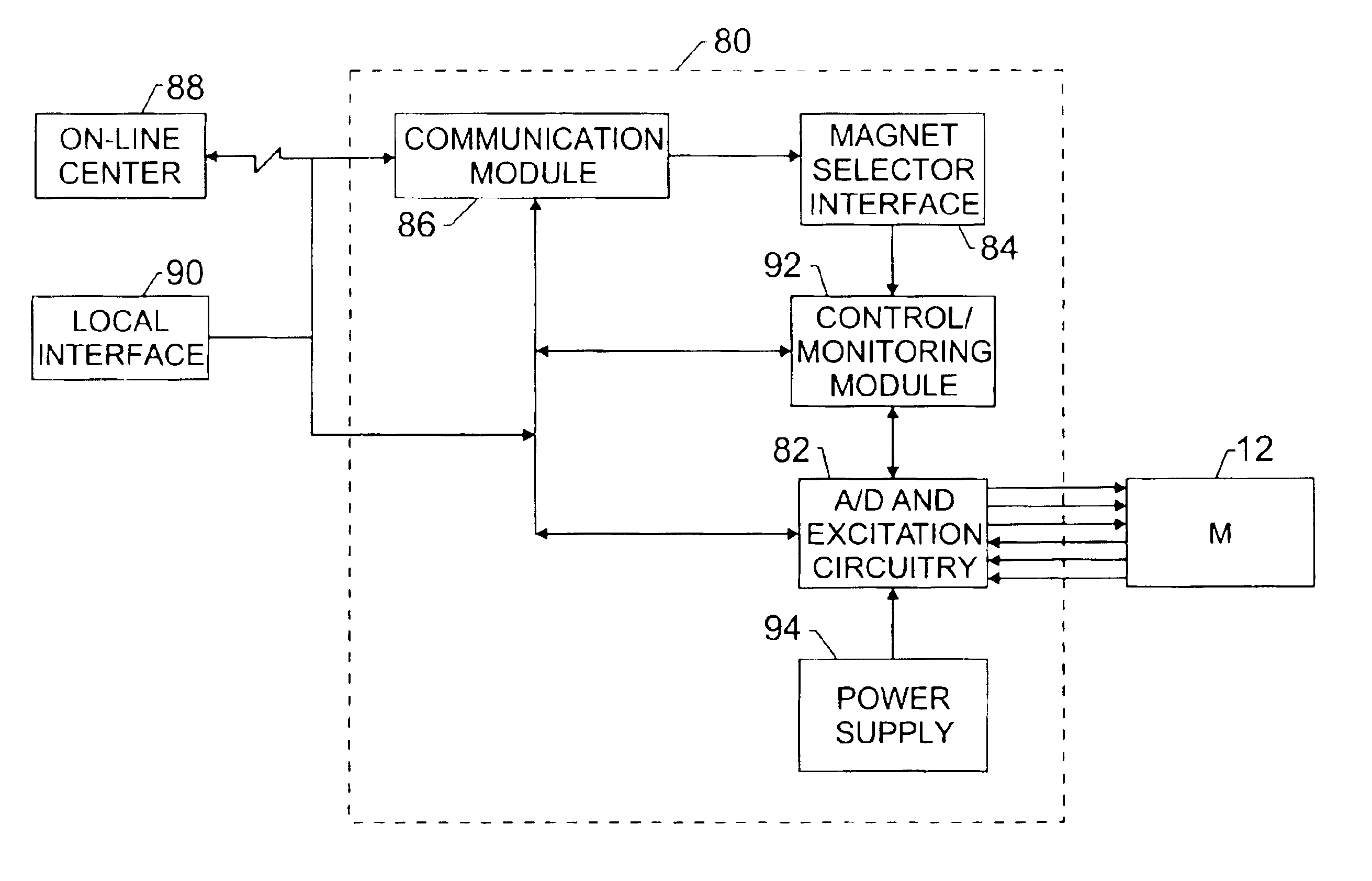
The present invention provides a novel technique designed to respond to such needs. The technique provides for remote monitoring of superconducting magnet systems of various types, manufacturers, vintages, and so forth. A magnet selector interface may be used to configure the monitoring system to the particular magnet system of interest. The magnet selection, for example, may be performed locally or downloaded by or from a service provider. Scalable analog-to-digital conversion reads output from the magnet system sensors and integrated excitation circuitry may scale excitation input to magnet system sensors. Devices, such as remote terminal units and other data-logging technology may be adapted to remotely monitor primary indicators and secondary indicators of magnet system performance and the related boil-off of helium. Primary indicators or variables that may be monitored include liquid helium level and pressure. In certain circumstances, primary indicators may also include, for example, helium temperature, radiation shield temperature, heater duty cycle, magnet current, and magnet field strength or frequency. Secondary indicators include, for example, operating variables and failures of the cold head, compressor, and other MRI devices. Set points for the primary and secondary indicators may be defined and compared against actual values. Alarm conditions may be specified with remote indication, for example, to a service technician and / or on-line center. The technique provides earlier warning of impending failures in the magnet system and facilitates predictive maintenance, reducing maintenance costs, MRI downtime, helium loss, and the like.

Problems solved by technology

Challenges exist, however, in maintaining the electromagnets at these extreme temperatures which are significantly lower than ambient temperatures.
Cryogenic liquids, such as liquid helium, however, are relatively expensive to produce and maintain.
Therefore, older approaches of “open” systems which have no recondensing capability and where cryogen vapor is normally vented to the atmosphere, have generally fallen out of favor in the industry.
In contrast, for recondensing magnets systems which recover the vaporized cryogen, losses in cryogen liquid level are not expected during normal operation.
Recondensing magnet systems, however, from time to time, require maintenance, for example, when the cryogen condensing system may require repair or replacement.
In particular, the performance of the condensing system components may degrade, thereby reducing the efficacy of the condensing system and overall magnet cooling system (cryogenic cooling system).
Moreover, leaks within the cryogen (helium) vessel and / or condensing system, again for example, may also reduce the efficacy of the cooling system.
If the cryogen condensing system is off-line or not condensing effectively, more of the liquid cryogen may begin to volatilize, leading to an increase of pressure in the cryogen vessel (i.e., cryostat).
This conversion of liquid cryogen, such as liquid helium, to its gaseous state, and / or the subsequent venting of the gas, is generally known in the industry as “boil-off.” Venting of the gas leads to permanent loss of expensive cryogen, requiring periodic refilling of the system.
In contrast, with “open loop” thermal designs, such as those without recondensing technology, the expected boil-off results in a measurable drop in liquid level in the vessel over time.
Such approaches are proving to be generally inadequate for recondensing systems.
For example, certain parts and / or technicians may not be immediately available, leading to longer than necessary downtimes (i.e., off-line time).
Moreover, periods of reactive maintenance may not coincide with already scheduled routine maintenance procedures, leading to duplicative downtimes for the MRI device.
Similarly, when substantial quantities of cryogen are required, very significant costs may be incurred in refilling the serviced system.
Similar problems exist even prior to the time such magnets are placed in operation.
Current procedures for building, testing and shipping superconductive magnets do not, however, adequately accommodate boil-off or servicing needs.
In much the same way, mobile MRI systems and systems where communications infrastructures are less available pose particular challenges beyond those of traditional fixed locations in hospitals.
Such challenges include cryogen monitoring and servicing; but also location and identification of the systems, and communication of relevant parameter data to a monitoring or service-coordinating location.

Method used


Image

  • Method and apparatus for monitoring superconducting magnet data
  • Method and apparatus for monitoring superconducting magnet data
  • Method and apparatus for monitoring superconducting magnet data

Examples


Embodiment Construction

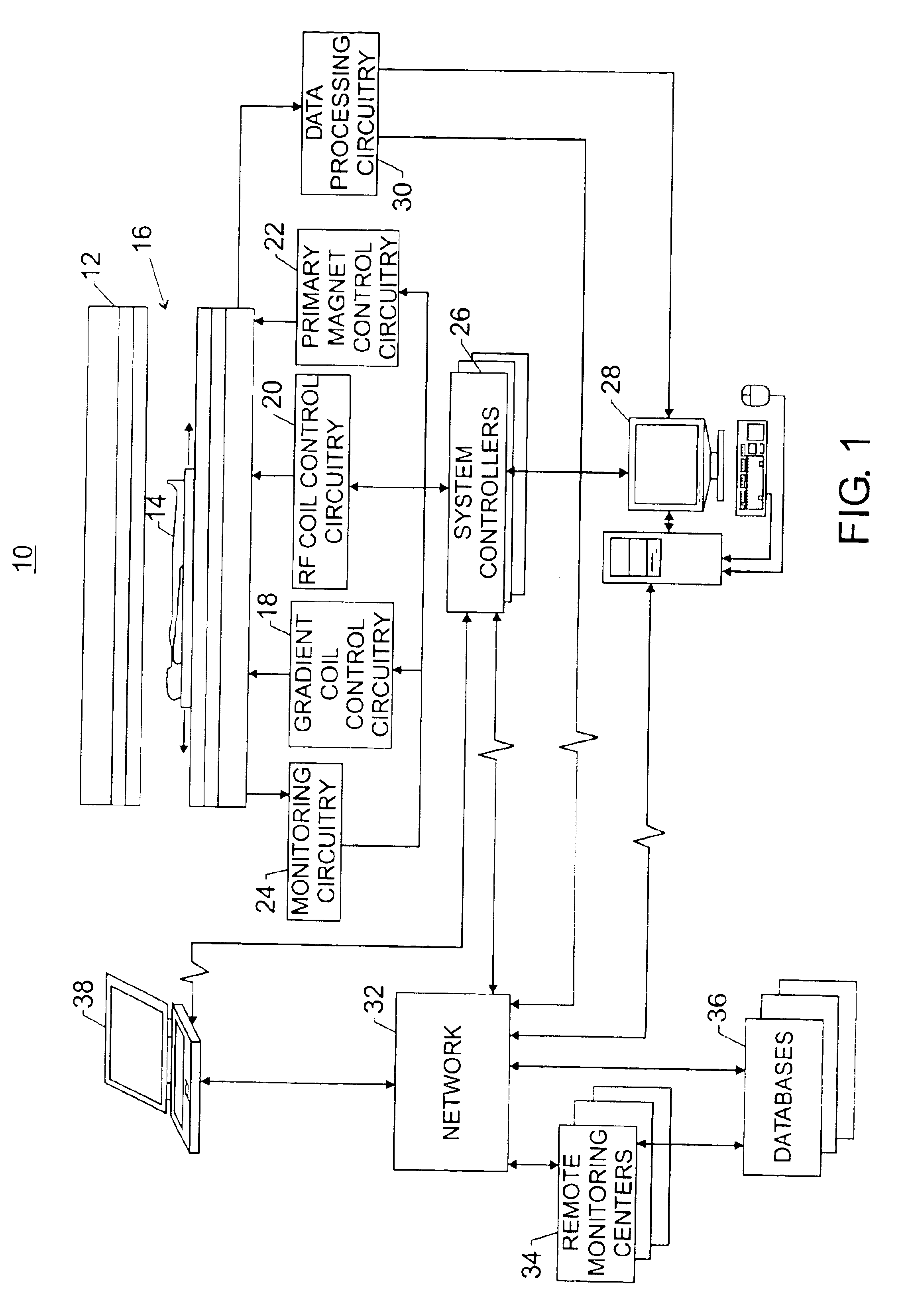
Turning to the drawings, and referring first to FIG. 1, an exemplary imaging network 10 is illustrated. Although the present technique is described with respect to a medical imaging device, it should be note that the present technique may be applied to any number of systems or devices that employ a cryogen cooling system, such as spectroscopy systems, nuclear accelerators, biological cooling facilities, and power transmission systems, to name but a few. The exemplary imaging network 10 includes a magnetic resonance imaging scanner 12.

To obtain diagnostic images of a patient 14, a medical professional may direct the patient 14 into a patient bore 16 of the MRI scanner 12. A main magnetic field (e.g., 0.5-2.0 Tesla) is generally present in the patient bore 16. This field, as discussed further below, is produced by a superconductive electromagnet (see FIG. 2) disposed circumferentially about the patient bore 16. The superconductive electromagnet is maintained at superconducting tempera...


PUM


Abstract

Remote monitoring of superconducting magnet systems of various types, manufacturers, vintages, and so forth, via a magnet selector interface providing for configuring the monitoring system to the particular magnet system of interest. The technique provides for scalable analogue to digital conversion with integrated excitation circuitry for the input and output of magnet system sensors. Devices, such as remote terminal units and other data-logging technology may be adapted to remotely monitor primary indicators and secondary indicators of magnet system performance and related boil-off of helium. The technique provides earlier warning of impending failures in the magnet system, and thus facilitates predictive maintenance, reduces maintenance costs, reduces MRI downtime, reduces helium loss, and the like.

Description

BACKGROUND OF THE INVENTIONThe present technique relates to medical imaging devices and, more particularly, to imaging devices with cryogenic cooling systems.A number of important applications exist for superconductive magnet systems. These include imaging systems, as for medical imaging, as well as spectrometry systems, typically used in materials analysis and scientific research applications. The present technique relates to management of cryogenically cooled superconductive magnets, and particularly to the monitoring and servicing of such systems. Although reference is made throughout the following discussion to imaging systems, it should be borne in mind that the technique is applicable to a range of systems that utilize cryogenically cooled superconducting magnets.Imaging devices are omnipresent in typical medical and other environments. Medical practitioners, such as physicians, may employ medical imaging devices to diagnose patients. Imaging devices, such as Magnet Resonance ...

Claims


Application Information

Patent Timeline
IPC IPC(8): G01R33/38G01R33/3815
CPCG01R33/3815
Inventor KNIGHT, LARRY KEITHCHAN, PETER
Owner GE MEDICAL TECH SERVICES
Learn More