
Directory read inhibitor for optical storage media

Inactive Publication Date: 2005-01-04
FLEXPLAY TECH INC
View PDF101 Cites 56 Cited by
  • Summary
  • Abstract
  • Description
  • Claims
  • Application Information

AI Technical Summary

Benefits of technology

A goal of the invention is to simultaneously satisfy the above-discussed requirements of low cost, limited content lifetime, avoidance of rental returns and minimum changes to existing manufacturing processes which, in the case of the prior art, are not simultaneously satisfied.
One aspect of our invention consists of attacking solely, primarily or first the table of contents (or directory) information on an optical disk. This could be achieved by several approaches, such as a coating, modifying the properties of the substrate, or damaging the metal layer. Benefits include higher manufacturability because a smaller part of the disk may need to be rendered inoperable, and more abrupt deterioration, as instead of deteriorating parts of the video content on a DVD, possibly in a gradual process, attacking the table of contents will prevent the player from accessing entire sections of the video content, and render the disk unplayable in a relatively sharp time frame. This is likely to be preferable to having an extended period during which the disk is playable, but not at full quality. It should be noted that because of the much stronger error correction in the table of contents, previous approaches such as Smith et al, would likely result in the table of contents failing last. Our invention recognizes, however, the benefit of having the table of contents fail first. In order to make the table of contents (or any other part of the disk) more vulnerable the disk could be mastered with a lower level of error correction in this region, a small set of errors could be intentionally introduced in mastering or manufacturing, or a substrate or coating could be used which already was less-than-perfectly readable.
In a further improvement to other proposed approaches, an aspect of our invention consists of increasing the thickness of the material that interferes with reading of the optical data. For instance instead of a coating of a few microns, our invention would allow a layer of material up to the thickness of the substrate, possibly reaching all the way to the metal layer. That would facilitate interfering with the reading laser. For example, it would make it easier to absorb or reflect enough laser light to prevent the laser from reading the data on the disk. It would also make it substantially more difficult for a user to defeat this mechanism by polishing off a thin coating, either mechanically or through the use of a solvent. In one embodiment, this invention would consist of pores or trenches of appropriate dimensions that are imprinted on the substrate during the molding process, by using a specially engineered molding plate instead of the standard flat plate (“mirror”). In another embodiment the shape of these pores or trenches would help prevent the reading of data. For example, a trench (or set of pores) with angled walls over the directory area of a DVD could be filled with a material that changes its refractive index upon exposure to the environment, or physically shrinks allowing air, other gases or vacuum to fill in the gap, or expands. In any of these cases, after the change in the filling material occurs, the laser beam may be reflected at the boundary of the trench or its interior, thus being prevented from reliably reading the data on the disk.
In another aspect of our invention, small bubbles, crystals, particles or cracks could form in the coating or substrate, making the data unreadable. For instance a substance (in gas, solid or other state) could gradually precipitate or otherwise separate from other parts of the disk and thereby create interference for the light beam. In addition to potentially being easier to achieve than a uniformly increasing opacity, this approach may more successfully interfere with the readability of the disk.
In another embodiment, a water-soluble opaque substance over the table of contents or the entire surface of the disk would prevent the disk from being played. The user would need to wipe off with a wet cloth this substance, in order to make the disk playable. The water and moisture would then trigger the process that renders the disk unplayable. Other embodiments could require user actions such as heating or cooling the disk, squeezing or shaking, exposing to microwave radiation in a microwave oven, exposure to bright light, exposure to ultraviolet light dipping in water or other substances, wiping or otherwise exposing the disk to some chemical, or removing or changing some component of the disk. The users actions would relatively quickly render the disk (temporarily) playable. However, they would also set in motion a different and effectively irreversible sequence or set of reactions which eventually render the disk unplayable. The advantage of this general strategy is that instead of relying only or primarily on relatively passive environmental conditions to render the disk unplayable, our invention leads the user to take a more drastic action which may provider a sharper starting point for the time period before the disk becomes unplayable and expand the set of reactions and approaches which can be considered.

Problems solved by technology

Similarly, removal of the disk from a controlled environment (e.g., inside the packaging) could gradually render the disk unplayable.

Method used


Image

  • Directory read inhibitor for optical storage media
  • Directory read inhibitor for optical storage media
  • Directory read inhibitor for optical storage media

Examples


example 1

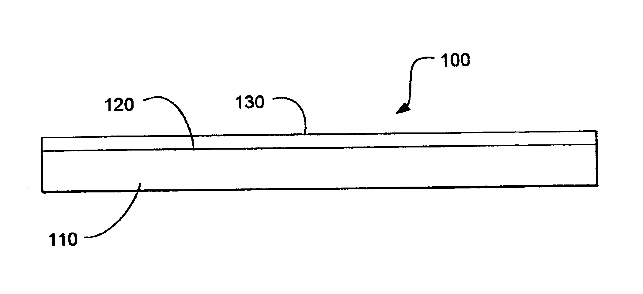
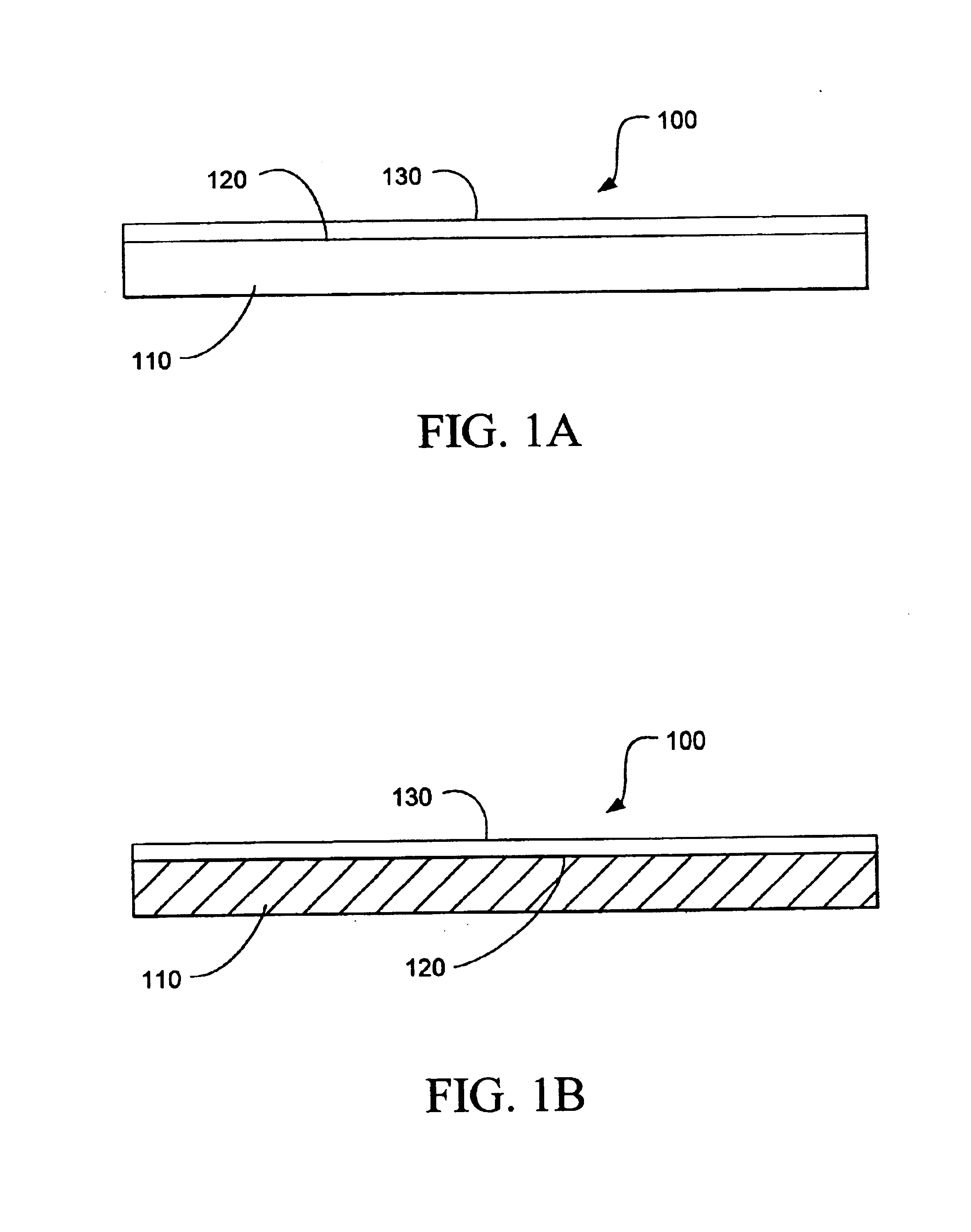
Referring to FIGS. 1a-1b, edge views of an optical disk 100 with a pseudo-transmissive read inhibitor are shown. The optical disk 100 includes a substrate 110, a reflective layer 120 and a lacquer layer 130. FIG. 1a shows the optical disk 100 in a first state wherein the substrate 110 is substantially optically transmissive. FIG. 1b shows the optical disk 100 in a second state wherein the substrate is substantially optically non-transmissive. The transformation from the first state to the second state is at-least-in-part a function of time from an initializing event, in this particular example, the opening of a substantially gas impermeable membrane (not shown) that encloses the optical disk 100 while it is packed, shipped and sold.

example 2

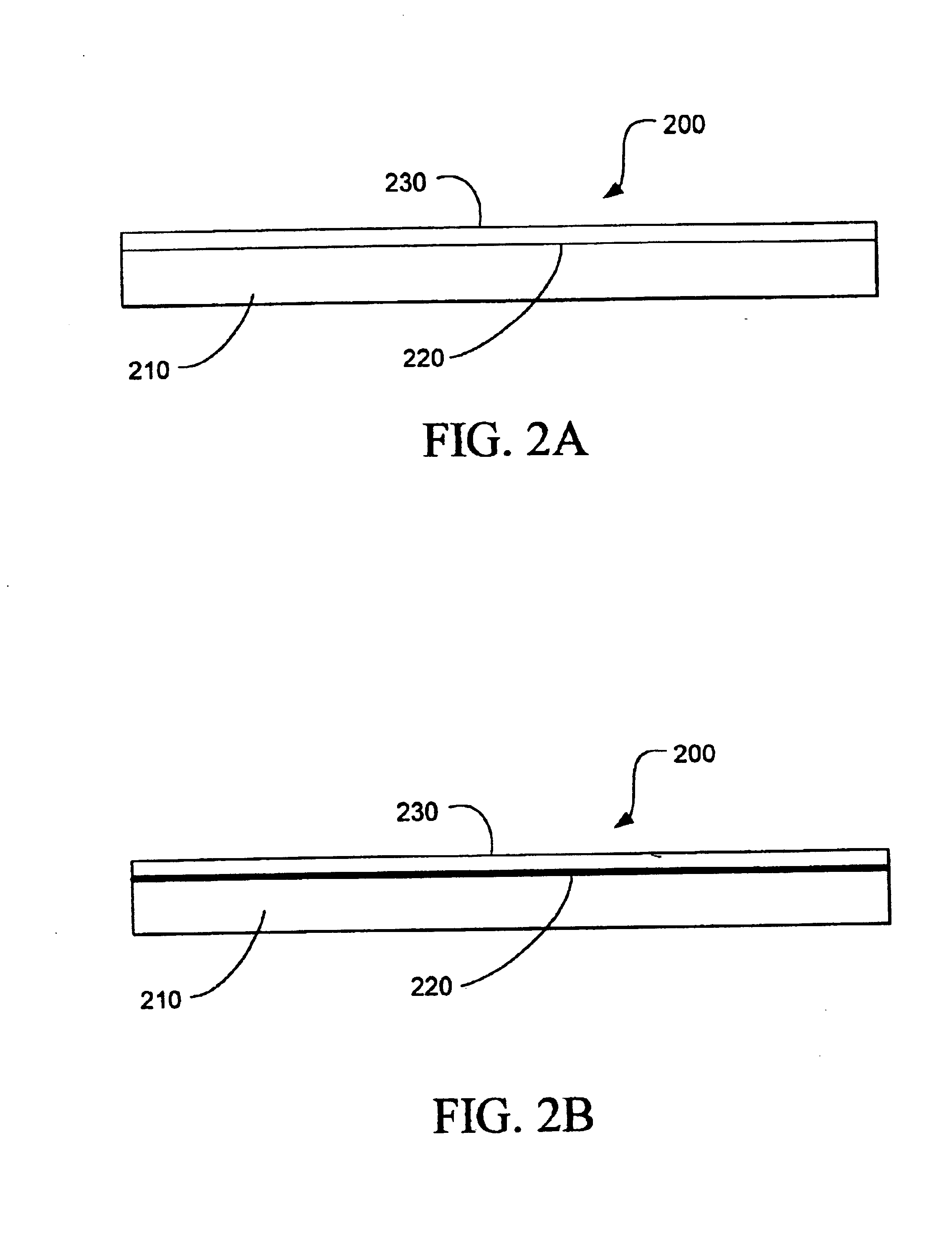
Referring to FIGS. 2a-2b, edge views of an optical disk 200 with a pseudo-reflective read inhibitor are shown. The optical disk 200 includes a substrate 210, a data encoded component 220 and a lacquer layer 230. In this example, the data encoded component 220 is a thin film of metal. FIG. 1a shows the optical disk 200 in a first state wherein the data encoded component 220 is substantially optically reflective. FIG. 1b shows the optical disk 200 in a second state wherein the data encoded component 220 is substantially optically non-reflective. As in the first example, the transformation from the first state to the second state is at-least-in-part a function of time from an initializing event, in this second example, the opening of a substantially air tight laminated polymeric container (not shown) that encloses the optical disk 200 while it is packed, shipped and sold.

Practical Applications of the Invention

A practical application of the invention that has value within the technologi...


PUM


Abstract

Systems and methods are described for inhibiting the readability of an optical media due to changes in a pseudo-reflective material that composes the optical media after the optical media has been exposed to air for a predetermined time. An optical media includes a data encoded component. At least a fraction of the data encoded component transforms from a substantially optically reflective state to a substantially optically non-reflective state as at-least-in-part a function of time from an initializing event. The systems and methods provide advantages because of low cost, limited content lifetime, avoidance of rental returns and minimum changes to existing manufacturing processes.

Description

BACKGROUND OF THE INVENTION1. Field of the InventionThe invention relates generally to the field of optical media. More particularly, the invention relates to time sensitive disposable optical media.2. Discussion of the Related ArtOptical disks such as CDs and DVDs are sold and rented to consumers for use at home. The content of the optical disks may be music, movies, software or data. Unfortunately, the purchase of CDs and DVDs can be expensive. The cost is associated not primarily with the manufacturing cost of the optical disks, but with the value of the information, such as movies or software, encoded on the disks. Content providers, such as movie studios or software companies, do not want to sell at a low cost copies of their material that will have a long lifetime in the marketplace. Rentals of CDs and DVDs enable consumers to access the information at a lower cost, but the need to return the rentals on time is inconvenient. It would be desirable to have an optical media (e.g....

Claims


Application Information

Patent Timeline
IPC IPC(8): G03G7/00G11B7/24G11B7/253G11B7/258G11B23/28G11B23/03G11B23/00G11B7/005G11B7/2534G11B7/254G11B7/2542G11B7/259G11B7/2595G11B7/26
CPCG03G7/0033G11B7/24G11B7/252G11B7/259Y10T428/21G11B23/0028G11B23/032G11B23/0327G11B23/282G11B7/2595G11B7/2534G11B7/2542
Inventor BAKOS, YANNISBRYNJOLFSSON, ERIK
Owner FLEXPLAY TECH INC
Learn More