
Hose

a technology of hoses and rubber layers, applied in the field of hoses, can solve the problems of insufficient adhesion between rubber layers and metal foil laminates, complex production processes, and high cost, and achieve the effects of less cost, light weight, and superior gas barrier properties

Inactive Publication Date: 2005-01-04
SUMITOMO RIKO CO LTD
View PDF13 Cites 8 Cited by
  • Summary
  • Abstract
  • Description
  • Claims
  • Application Information

AI Technical Summary

Benefits of technology

The inventors of the present invention conducted intensive studies to provide a hose which is superior in gas barrier properties, light in weight and less costly. The inventors initially came up with an idea to employ a hose of a laminated structure comprising a rubber layer and a metal foil laminate rather than the conventional metal tube for weight reduction, and focused attention on an ethylene-propylene-diene terpolymer (hereinafter abbreviated as “EPDM”) and an ethylene-propylene copolymer (hereinafter abbreviated as “EPM”) which are less costly as the material for the rubber layer. The inventors prototyped the hose by bonding the rubber layer and the metal foil laminate with an adhesive, but found that the adhesion between the rubber layer and the metal foil laminate was insufficient due to uneven application of the adhesive. With the need for an adhesive application step, the production process is complicated and more costly. In addition, consideration should be given to the pot life and concentration control of the adhesive, making it difficult to ensure stable production. Further, the production process presents a problem associated with environmental pollution because an organic solvent such as toluene is employed as a thinner for the adhesive.
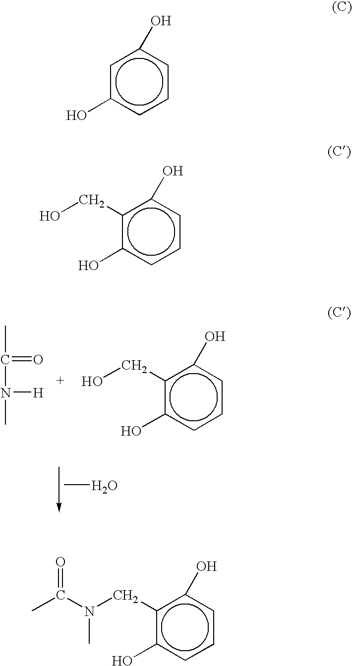
A reason why the rubber layer composed of the aforesaid specific rubber composition has excellent adhesion to the laminate is believed to be as follows. The resorcinol compound mainly functions as an adhesive, and the melamine resin mainly functions as an auxiliary adhesive agent. More specifically, the melamine resin donates CH2O to the resorcinol compound, which in turn forms covalent bonds with a resin (e.g., a polyamide resin) in the laminate thereby to improve the adhesion. For example, the melamine resin donates CH2O to a resorcinol compound represented by the following formula (C) to provide a compound represented by the following formula (C′), which in turn forms covalent bonds with polyamide linkages (—CONH—) of the polyamide resin in the laminate to ensure firm adhesion. In addition, hydroxyl groups of the resorcinol compound partly serve for hydrogen bonding with the polyamide groups in the polyamide resin. It is supposed that the hydrogen bonding also contributes to the improvement of the adhesive effect.

Problems solved by technology

The inventors prototyped the hose by bonding the rubber layer and the metal foil laminate with an adhesive, but found that the adhesion between the rubber layer and the metal foil laminate was insufficient due to uneven application of the adhesive.
With the need for an adhesive application step, the production process is complicated and more costly.
In addition, consideration should be given to the pot life and concentration control of the adhesive, making it difficult to ensure stable production.
Further, the production process presents a problem associated with environmental pollution because an organic solvent such as toluene is employed as a thinner for the adhesive.

Method used


Image

  • Hose
  • Hose
  • Hose

Examples


example 1

Preparation of Rubber Composition

First, 100 parts of the above EPDM, 4.2 parts of the above peroxide vulcanizing agent, 1 part of the above resorcinol compound, 0.77 parts of the above melamine resin, 100 parts of the above carbon black and 60 parts of the above process oil were blended, and then the resulting mixture was kneaded by means of a roll mill for preparation of a rubber composition.

Production of Hose

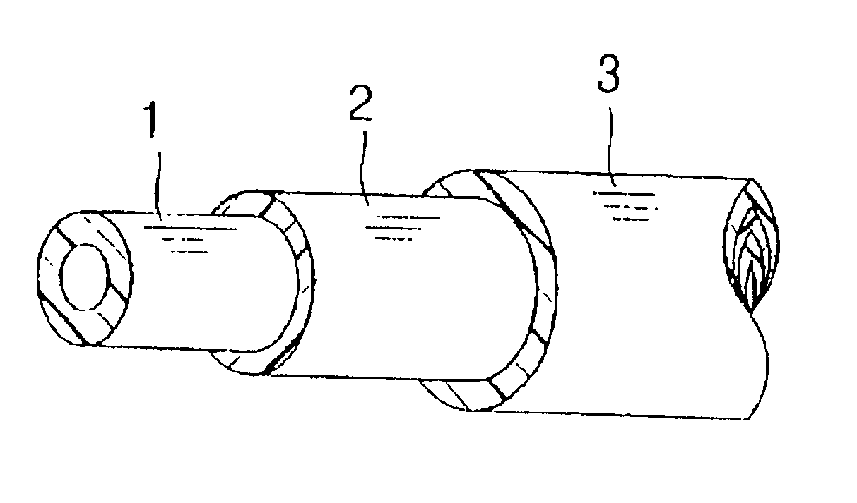
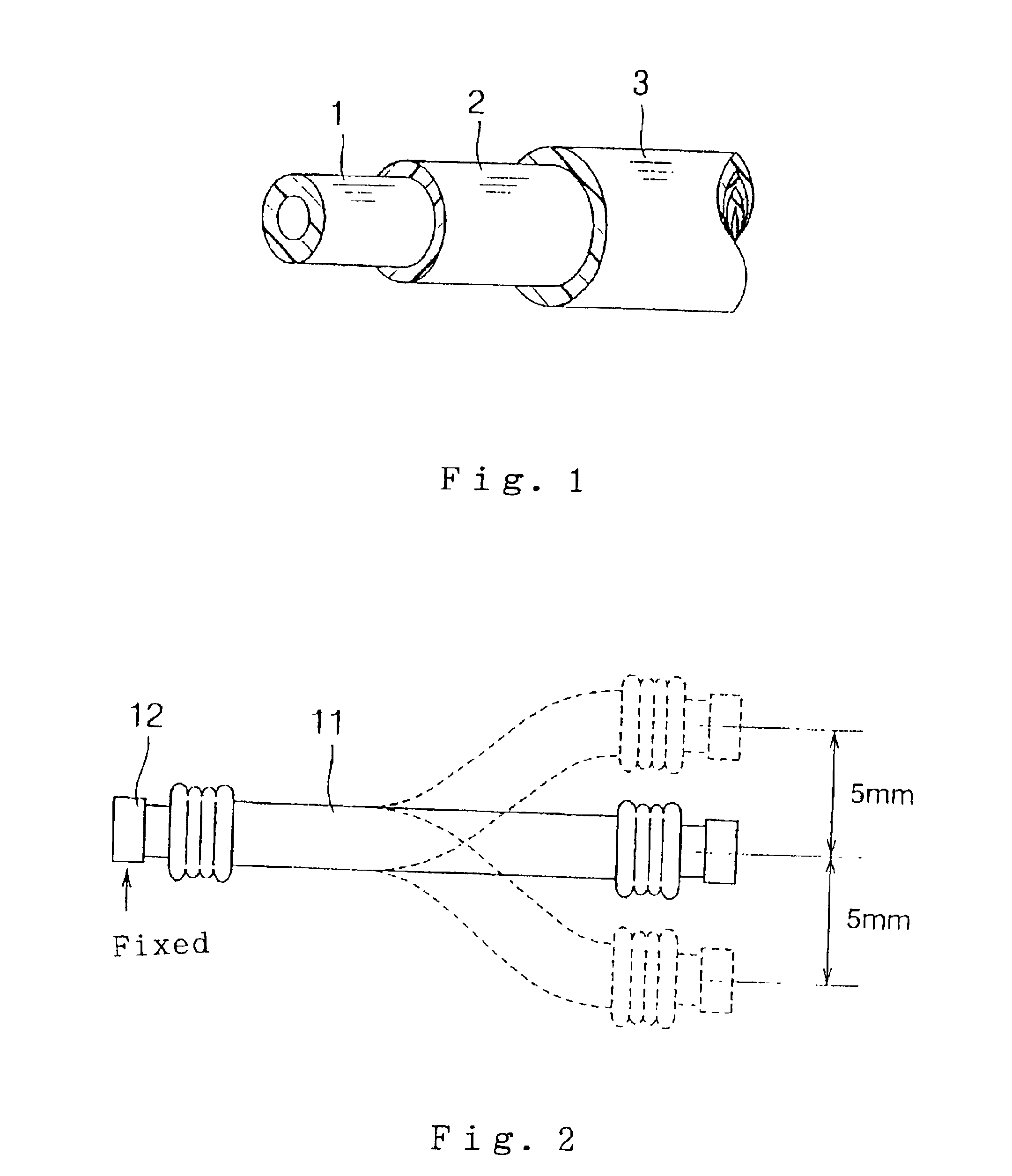
The rubber composition thus prepared was extruded around a mandrel for formation of an unvulcanized rubber layer, and then a laminate film (PA6 film / SUS foil / PA6 film) having a total thickness of 70 μm was wrapped on an outer peripheral surface of the unvulcanized rubber layer for formation of a laminate. Then, the rubber composition was extruded on an outer peripheral surface of the laminate. After the resulting hose structure was entirely subjected to a vulcanizing process at 160° C. for 45 minutes, the mandrel was removed. Thus, a hose (see FIG. 1) was produced, which inclu...

example 13

Preparation of Rubber Composition

First, 100 parts of the above EPDM, 4.2 parts of the above peroxide vulcanizing agent, 1 part of the above resorcinol compound, 0.77 parts of the above melamine resin, 100 parts of the above carbon black and 60 parts of the above process oil were blended, and then the resulting mixture was kneaded by means of a roll mill for preparation of a rubber composition.

Production of Hose

The rubber composition thus prepared was extruded around a mandrel for formation of an unvulcanized rubber layer, and then a laminate film (PA6 film / aluminum foil / PA6 film) having a total thickness of 70 μm was wrapped on an outer peripheral surface of the unvulcanized rubber layer for formation of a laminate. Then, the rubber composition was extruded on an outer peripheral surface of the laminate. After the resulting hose structure was entirely subjected to a vulcanizing process at 160° C. for 45 minutes, the mandrel was removed. Thus, a hose (see FIG. 1) was produced, which ...


PUM

PropertyMeasurementUnit
Percent by massaaaaaaaaaa
Fractionaaaaaaaaaa

Abstract

A hose of a laminated structure which comprises a rubber layer composed of a rubber composition, and a laminate including a metal foil and a resin, the rubber composition including:(A) a rubber including at least one of an ethylene-propylene-diene terpolymer and an ethylene-propylene copolymer;(B) a peroxide vulcanizing agent;(C) a resorcinol compound; and(D) a melamine resin.The hose is light in weight, less costly, and has excellent gas barrier properties.

Description

BACKGROUND OF THE INVENTION1. Field of the InventionThe present invention relates to a hose and, more specifically, to a hose for automotive use, for example, for use as a methanol fuel hose or a hydrogen fuel hose in a fuel cell vehicle or a hose for transporting coolant in an air conditioner.2. Description of the ArtMotor vehicles employing a methanol fuel (which may contain a gasoline) or a hydrogen fuel have not come into practical use, so that hoses for use in such motor vehicles have not specifically been developed. However, attempts are actively made to equip next-generation automotive systems with fuel batteries employing a methanol fuel or a hydrogen fuel, and there is an increasing demand for developing hoses such as a methanol fuel hose and a hydrogen fuel hose for use in fuel cell vehicles.Metal tubes such as of stainless steel (SUS) are currently employed as fuel tubes (e.g., methanol fuel tubes and hydrogen fuel tubes) for fuel cell prototype vehicles pre-produced by a...

Claims


Application Information

Patent Timeline
IPC IPC(8): B32B1/00B32B1/08B32B25/04B32B25/00B32B15/08C08L23/00C08L23/16F16L11/04C08L79/00C08L79/08
CPCB32B15/08C08L23/16F16L11/04B32B25/04Y10T428/1352C08L79/08F16L2011/047Y10T428/1383Y10S138/07Y10S138/10Y10S138/04Y10T428/1386Y10T428/1359Y10T428/1393Y10T428/1379Y10T428/1355C08L2666/20Y10T428/3175Y10T428/31757Y10T428/31692Y10T428/31681Y10T428/31746Y10T428/31938B32B2311/18B32B2311/12B32B2311/08B32B1/08B32B2311/30B32B2311/22B32B2311/24B32B2457/18B32B7/12B32B15/06B32B2605/00B32B15/20B32B2323/16B32B15/18B32B2377/00B32B25/08
Inventor IKEMOTO, AYUMUHIBINO, MOTOSHIGEIKEDA, HIDEHITOKATAYAMA, KAZUTAKA
Owner SUMITOMO RIKO CO LTD
Learn More