
Cap feeding apparatus for a fastener gun

a technology of fastener gun and feeding apparatus, which is applied in the direction of nailing tools, cloth making applications, book covers, etc., can solve the problems of time-consuming and inefficient manual placement of caps, and serious safety hazards for operators, so as to reduce height, improve the view of caps, and shorten the shuttle stroke

Active Publication Date: 2005-01-04
PNEUTOOLS
View PDF14 Cites 32 Cited by
  • Summary
  • Abstract
  • Description
  • Claims
  • Application Information

AI Technical Summary

Benefits of technology

A second preferred common feature of all three embodiments is that, when the shuttle is in the cap-ejecting position, the rearward edge of the shuttle engages the leading portion of the leading cap in the magazine, while the trailing portion of the leading cap in the magazine is retained by a biasing spring. As the shuttle reciprocates from the cap-ejecting position to the cap receiving position, the rearward edge of the shuttle slides over the face of the leading cap in the magazine and between the biasing spring and the trailing portion of the leading cap. As the shuttle continues its reciprocation into the cap-receiving position, and the forward edge of the shuttle just passes the trailing portion of the leading cap, the leading cap is pushed from the magazine to a position in the feeding chamber immediately below the forward edge of the shuttle so that the shuttle, upon reversing the direction of reciprocation, can pull the leading cap through and then out of the feeding chamber. This use of both edges of the shuttle, with the rearward edge of the shuttle retaining the leading portion of the leading cap when the shuttle is in the cap-ejecting position in combination with the in spring retaining means engaging the trailing portion of the leading cap in the magazine, and with the forward edge of the shuttle feeding the leading cap from the magazine and out of the feeding chamber, allows the shuttle to have greatly reduced height above its leading edge, thereby allowing the cap feeding apparatus to be much closer to the nose of the gun and permitting a shorter shuttle stroke and lighter-weight cap feeding apparatus than heretofore possible.
It is an object of the present invention to provide for easier and more rapid installation of cap washers using a fastener-driving gun than heretofore possible.

Problems solved by technology

Application of such plastic cap washers to hold down roofing paper or tar paper wrapping is manual, tedious, and slow.
The manual placement of caps presents a serious safety hazard to the operator because the operator's hand is close to the nose of the gun.
In addition, manual placement of caps is time-consuming and inefficient.
This is very time consuming and difficult, not only hard on the back but hard on the fingers.
For example, prior art cap feeding devices are generally heavy, putting additional stress on the operator's hand holding the fastener gun.
Also, many prior art cap feeding devices can only be installed close to the front end of a fastener gun, making the fastener gun not only heavy but also unbalanced with most of the weight placed at the front end of the gun.
This makes the nail or staple gun difficult to handle and may put stress on the operator's hand and wrist.
In addition, with so many components placed at the front end or side of the tool it is difficult to see the position of the nose of the gun, making a precise placement of the nail difficult.

Method used


Image

  • Cap feeding apparatus for a fastener gun
  • Cap feeding apparatus for a fastener gun
  • Cap feeding apparatus for a fastener gun

Examples


first embodiment

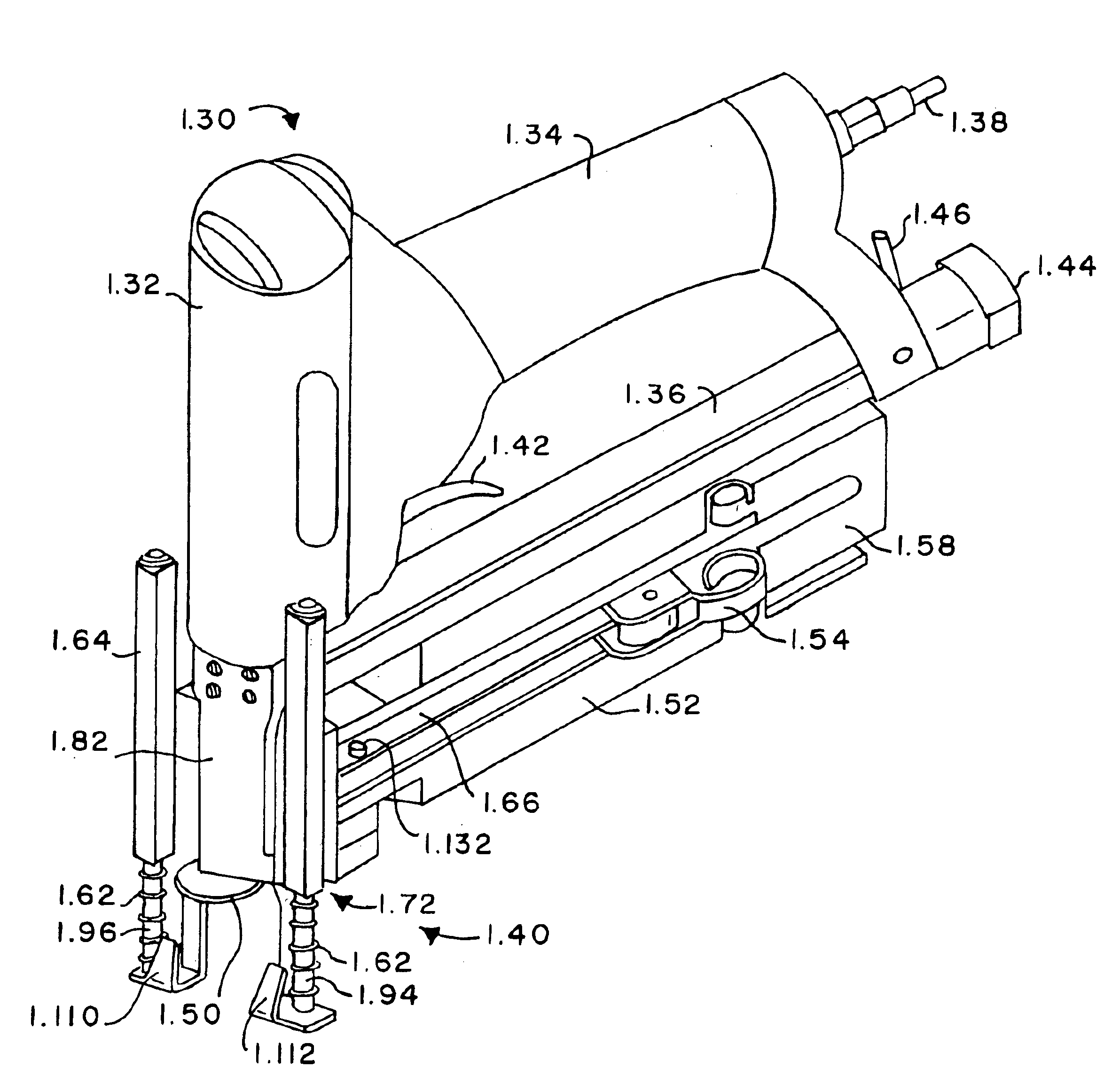
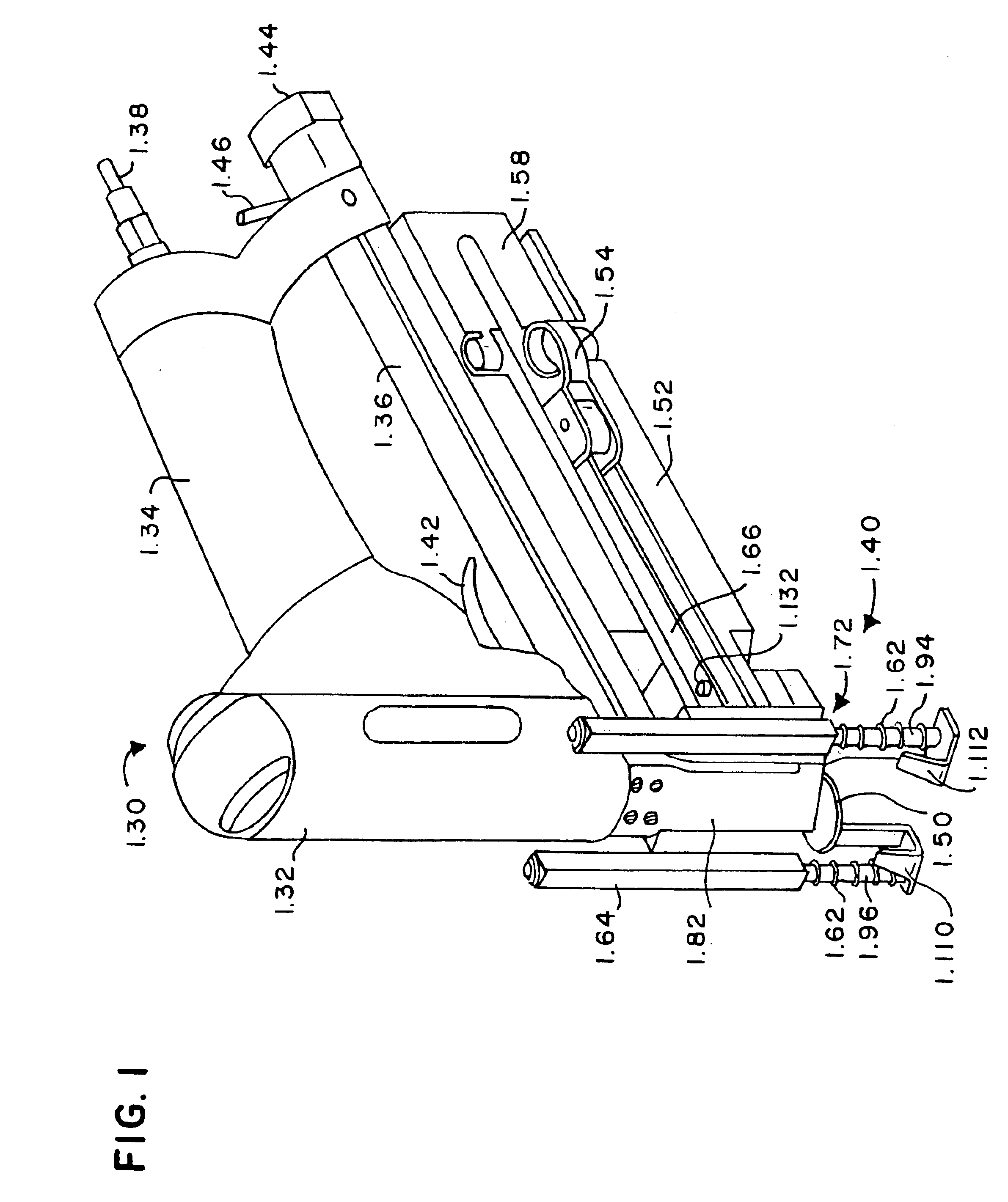
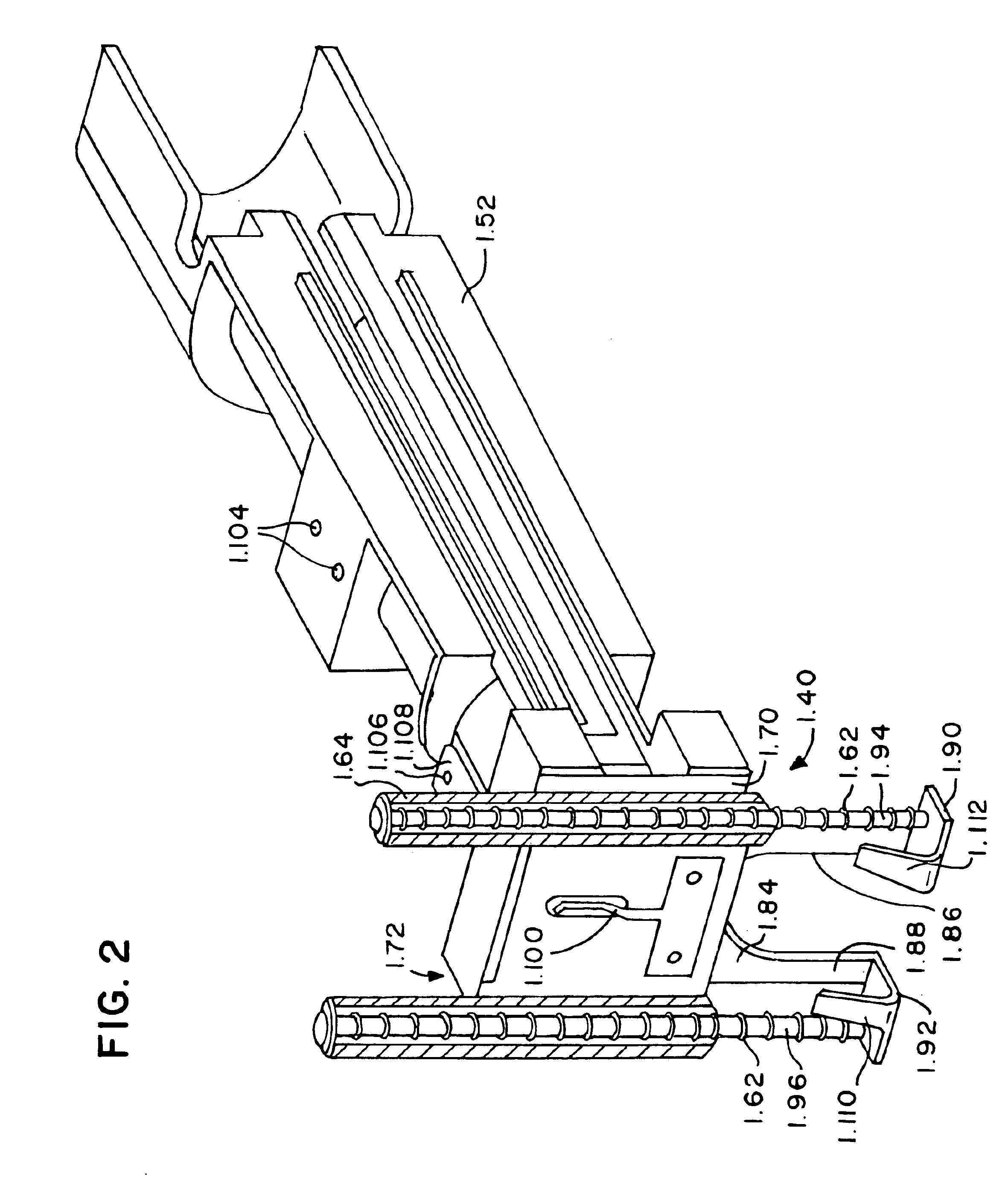
FIG. 6A is a cross section of the same area as FIG. 5A but is showing that the shuttle has been pushed upward into the cap receiving position. It should be noted that the spring arm 1.100 has been pushed out of the track area 1.114 by the beveled rearward edge 1.102 of the shuttle 1.84, and the rearward edge of the shuttle has now become interposed between the spring arm 1.100 and the leading cap 1.50. The forward edge 1.138 of shuttle 1.84 is preferably downwardly concave for best engagement with the leading cap 1.50 during the downward stroke and, in the present invention, the forward edge 1.138 of the shuttle is generally downwardly “U” shaped. When the shuttle is in the cap-receiving position (upward) as shown in FIGS. 6A and 6B, the leading cap can and does emerge from the cap magazine 1.52 in response to urging by the pusher 1.56, and moves into substantial coplanar relationship with the shuttle, forward of the shuttle's forward edge.

FIG. 7A is also a cross-section of the fron...

third embodiment

A suitable top-load pneumatic coil nail gun 3.30 for use with the third embodiment is a model number C21 / 50 LN-A1 coil nail gun made and sold by Basso Corp., NO.24 36th Rd., Taichung Ind. Park, Taichung, Taiwan, R.O.C.

FIG. 18 is a front side view of the cap feeding system mounted on a pneumatic coil nail gun 3.30 that is not a bottom-load tool 2.30 (see FIG. 14). It is a top-load tool. This also shows how the shuttle 3.84 does not need to separate from the air cylinder shaft 3.190. It shows how a bolt 3.199 and nut keep these two items connected at all times. To load this tool with nails you would push down on the door latch 3.197 which would pivot open on the door hinge pin 3.196 this in turn would allow you to open the back magazine cover 3.198. Once this has been done you would install the coil nails into the magazine and feed them into the nose and then close the nose door 3.185.

FIG. 19 is a back side view of the cap feeding system mounted on a pneumatic coil nail gun 3.30. It i...


PUM


Abstract

A construction tool and method of use for affixing holding cap washers to roofing paper and building wrap tar paper. The tool is a combination of a fastener-driving gun together with a feeding magazine holding a clip of plastic cap washers to be affixed, and the feed magazine feeds successive cap washers under the nose of the fastener-driving gun so that fasteners, such as nails or staples, can penetrate the cap washer and hold down the roofing paper or building wrap tar paper. As the cap approaches the nose of the gun, the cap feeder flips the cap ninety degrees along an axis transverse to the feed direction. A shortened shuttle is used with a spring arm holding one edge of the leading cap in the magazine and the rearward portion of the shuttle holding the other edge of the leading cap.

Description

STATEMENT REGARDING FEDERALLY SPONSORED RESEARCH OR DEVELOPMENTNot applicable.REFERENCE TO COMPACT DISC(S)Not applicable.BACKGROUND OF THE INVENTION1. Field of the InventionThe present invention relates, in general, to building construction tools, and in particular, to fastener driving tools for driving staples and nails and the like through cap washers.2. Description of Related ArtIt is often desired to use plastic cap washers to hold down roofing paper and so-called building wrap tar paper. Well-known solutions for this problem include providing plastic cap washers in bulk, each having a nail pre-inserted through the plastic cap washer, and a hammer is then used by a construction worker to pound the nail through roofing paper or tar paper wrapping and into a building. Application of such plastic cap washers to hold down roofing paper or tar paper wrapping is manual, tedious, and slow.Automatic nail and staple guns, powered by compressed air or electricity, are used, for example, t...

Claims


Application Information

Patent Timeline
IPC IPC(8): B25C5/00B25C5/16
CPCB25C5/1693
Inventor LAMB, FREDERICK W.
Owner PNEUTOOLS
Learn More