Corer-grinder

a corer-grinder and rotary technology, applied in the field of low mass, multi-functional geologic sampling and coring devices, can solve the problems of adding bulk and weight, affecting the accuracy of coring, so as to reduce the diameter of the tip and eliminate any chance of jamming

Inactive Publication Date: 2005-01-04
NG TZE CHEUN +3
View PDF2 Cites 12 Cited by
  • Summary
  • Abstract
  • Description
  • Claims
  • Application Information

AI Technical Summary

Benefits of technology

The present invention adds the function of gripping, as with tweezers or forceps, to the coring and automatic extraction of samples from the inside of rocks. Embodiments of the invention weigh no more than one pound (450 gm.) and can be used to core into rocks with a backing force of no more than 4.5 pounds (20 newtons), which is most suitable for interplanetary sampling expeditions where mass of the instrument and the lack of backing force are of prime consideration. The embodied coring head has a unique design that cores into rocks to a depth of 0.4 inches (10 mm) and can grip the samp

Problems solved by technology

However, underwater sampling apparatus require many bulky features to permit the apparatus to function at relatively high ambient pressures.
These features, such as thick-walled steel construction and—in the case of the Sheryll device—means for injecting fluids at high pressure to equalize internal and ambient pressures, add bulk and weight that make interplanetary transportation unfeasible or prohibi

Method used


Image

  • Corer-grinder
  • Corer-grinder
  • Corer-grinder

Examples


Embodiment Construction

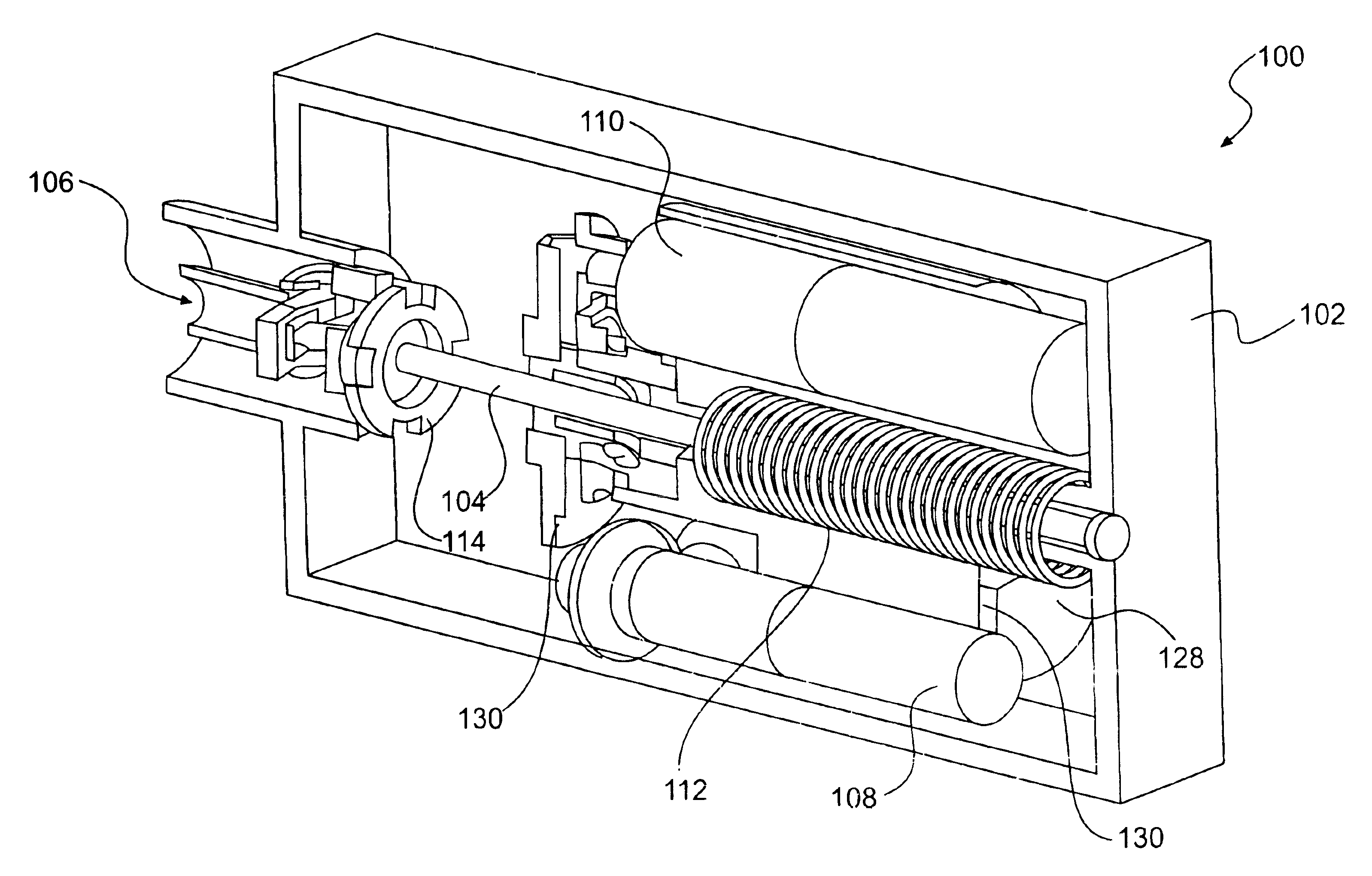
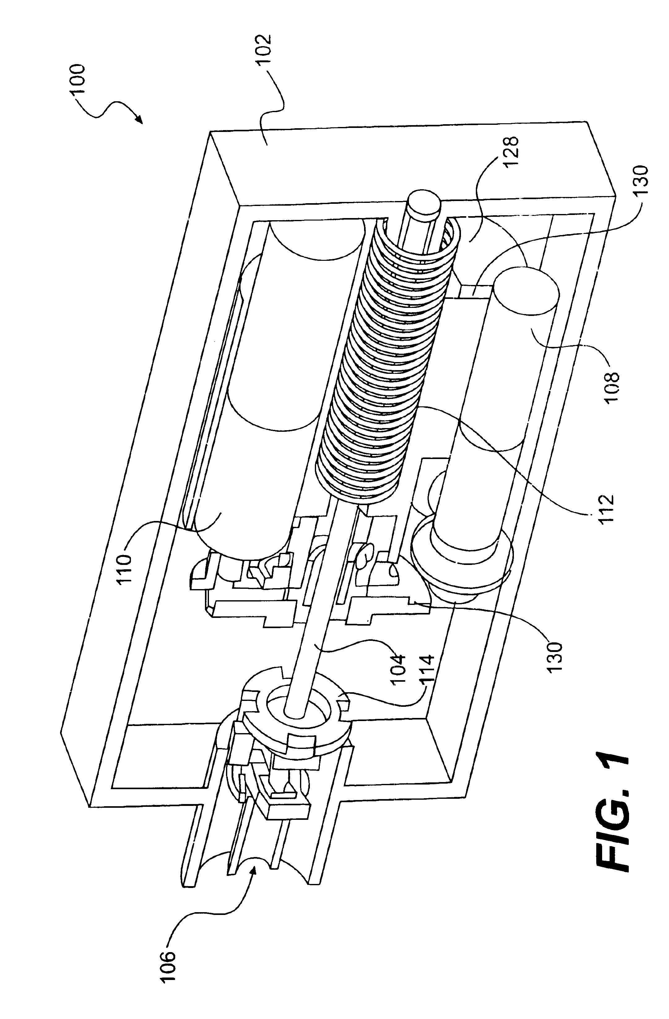
FIG. 1 is an orthogonal view of the corer sampler element, represented generally as 100, of the corer grinder apparatus of the present invention. Housing 102 encases a shaft 104 that is connected to claw assembly 106. Shaft 104 is located through the middle of hammer unit 130 which houses the drive motor 108 and coupling motor 110. Both motors are positioned proximate one end of housing 102 that is opposite the end of housing 102 proximate the claw assembly 106. During coring, both drive motor 108 and coupling motor 110 inside the housing 102 will rotate. Coupling motor 110 turns a coupling that transmits the rotary motion to shaft 104 which extends from the motor end of housing 102, passing through coil strike spring 112, beyond which shaft 104 connects to claw assembly 106. Drive motor 108 rotates a large gear 128 (not shown) that lifts the entire hammer unit 130 and simultaneously compresses spring 112. As persons of ordinary skill will recognize, means other than a gear may be u...


PUM


Abstract

A novel corer and grinder apparatus suitable for interplanetary travel and extraplanetary operation is disclosed. The corer grinder composes a claw element attached to a shaft coupled to a motor. A second motor compresses a spring forcing against a hammer unit that constitute the majority of the unit's mass. On release the energy stored in the compressed spring converts into momentum of the hammer unit that strikes against the claw element releasing the impact energy directly to the cutting end for cutting. The direction of the energy released is modified by an impact platform to produce a horizontal chipping action to aid cutting. The claw element further comprises a pair of semi-cylindrical claw elements that separate upon rotation of the shaft in a first direction, easing collection of core samples. The semi-cylindrical claw elements join upon rotation of the shaft in the opposite direction, thereby grasping the core sample during removal from the material being sampled. Operation of a third motor during rotation of the shaft extends and orbitally moves an X-Y table that permits the corer grinder to operate as a surface grinder over a relatively large surface area. Floating couplings of the claw elements minimize the transmission of vibration to internal elements of the corer grinder.

Description

BACKGROUND OF THE INVENTIONThis invention relates generally to a sampling and coring device for conducting geologic field work. More particularly, this invention relates to a low mass, multifunctional geologic sampling and coring device for interplanetary travel and for use in an extraplanetary environment, specifically Mars. Such extraplanetary operation includes collection of soil and rock samples in an uncontaminated, unchanged form at Martian ambient conditions.Modern scientific research methods, particularly those involving handling and analysis of small objects, are conducted with the consensus that properly designed tweezers can greatly extend the functionality of the human hands. This consensus is demonstrated by the fact that tweezers are the most common hand instruments used in scientific laboratories. This fact was central to the development of the Space Holinser Forceps System, which has helped astronauts work under zero or micro gravity. The Space Holinser Forceps syste...

Claims


Application Information

Patent Timeline
IPC IPC(8): G01N1/04G01N1/08
CPCG01N1/08
Inventor NG, TZE CHEUNYUNG, KAI LEUNGYU, CHUN HOCHAN, CHIU CHEUNG
Owner NG TZE CHEUN
Why Eureka
Try Eureka