
Jar opener assembly

Active Publication Date: 2005-01-04
HELEN OF TROY LIMITED
View PDF14 Cites 6 Cited by
  • Summary
  • Abstract
  • Description
  • Claims
  • Application Information

AI Technical Summary

Benefits of technology

The present invention provides for a jar opener assembly for removing a lid from a jar, the assembly comprising a torquing tool including a main body having a first side and a second side, the first side having a lid receiving cavity having at least a pair of edges to apply torque to the lid received therebetween, a second side having a pad receiving area, a handle protruding from the body and a pad removably mounted to the pad receiving area wherein the assembly may be used to open the jar by removing the pad from the main body of the torquing tool and placing it under the jar and placing the torquing tool on the jar so that the lid is received within the lid receiving cavity and torque is applied to the lid and the pad helps to restrict rotation of the jar so that the lid may be more easily rotated and removed from the jar.
The invention further provides for a jar opener tool for removing a lid screwed to a jar located on a countertop by placing a torquing tool over the lid and applying torque, the tool comprising a pad having a jar bottom abutment area formed of a high friction material, a countertop abutment area opposite the jar bottom abutment area formed of a high friction material and a torsion restriction area formed between the jar bottom abutment area and the counter top abutment area wherein upon application of torque to the lid, the jar rotates counterclockwise imparting a counterclockwise torsion to the jar bottom abutment area of the pad that is transferred to the torsion restriction area that is restricted from rotating by the countertop abutment area that is restricted from rotating due to high friction generated against the countertop so that the jar bottom abutment area restricts the jar from rotating and the lid may be easily removed upon continued application of torque by the torquing tool.

Problems solved by technology

While the known torquing tools are able to apply a sufficient amount of torque to the lid, such tools are difficult to operate efficiently because upon application of the torque, the jar will rotate, lessening the ability to remove the lid.
Although a user's other hand is grasped around the outer diameter of the jar, such gripping force is sometimes insufficient in order to hold the jar against the required torque necessary to unscrew the lid from the jar.

Method used


Image

  • Jar opener assembly
  • Jar opener assembly
  • Jar opener assembly

Examples


Embodiment Construction

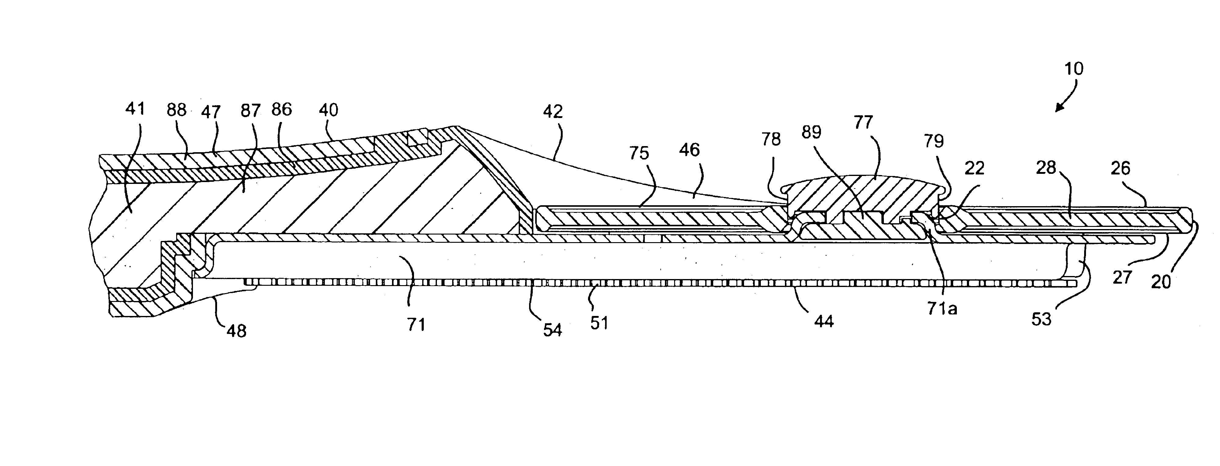
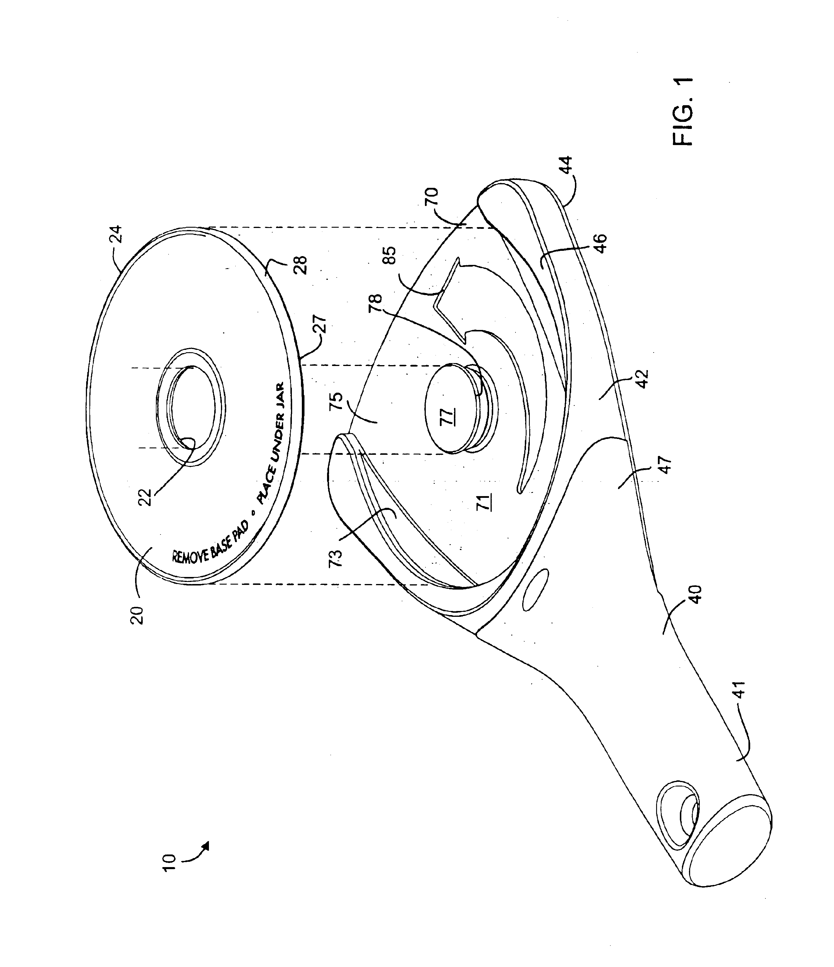
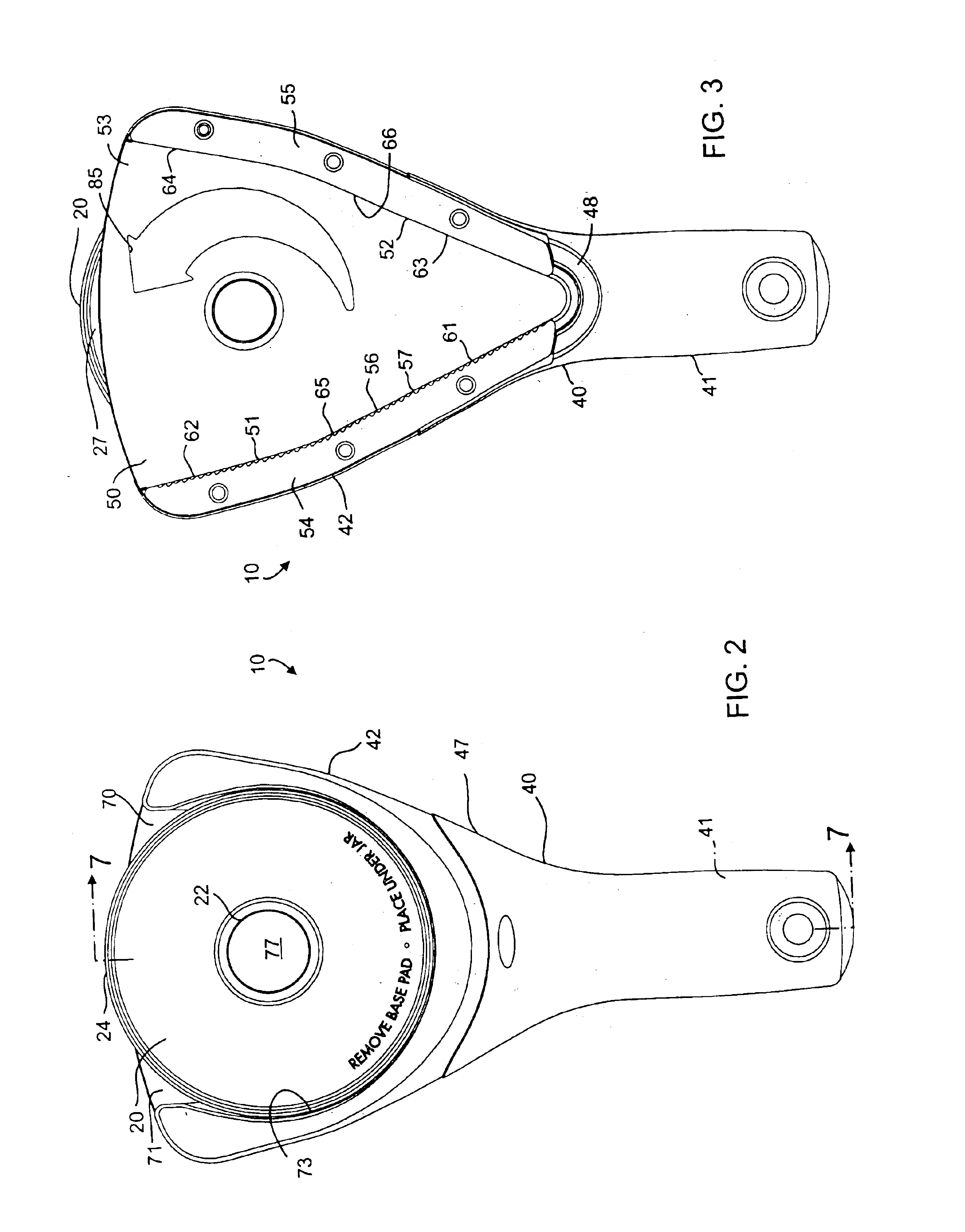
An embodiment of the present invention is described with reference to FIGS. 1-7. A jar opener assembly 10 includes a circular pad 20 that includes a central aperture 22 therethrough defining an inner diameter and a rim 24 formed at its outer diameter. The pad 20 in an embodiment is formed of a polymer material, for example, a thermoplastic resin or silicone. The pad forms a jar bottom abutment area 26, a counter top abutment area 27 and a torsion restriction area 28 formed therebetween. The pad 20 acts as a jar opening tool when it is placed under a jar so that the jar bottom abutment area 26 frictionally engages the bottom of a jar 30, and the countertop abutment area 27 frictionally engages a countertop 35 or other horizontal support surface upon which the pad 20 is placed (see FIG. 6). While the main use of the pad 20 is on the bottom of a jar 30, opposite a torquing tool 40, the pad 20 may also be used in certain circumstances on a lid 32 of a jar 30.

The torquing tool 40 include...


PUM


Abstract

The present invention pertains to a jar opener assembly including a torquing tool and a pad which are used in conjunction with each other in order to easily remove a lid from a jar by placing the pad under the jar and attaching the torquing tool so that a cavity having serrated edges abuts against the jar lid in order to apply torque thereto. The torquing tool includes a pad receiving area to which the pad is mounted when not in use.

Description

The present invention pertains to a kitchen utensil, and in particular, a jar opener assembly having a torquing tool and a pad for use therewith.BACKGROUNDJar openers are well known that are formed of a torquing tool having a handle and a lid receiving cavity formed in a V-shape. The V-shaped cavity is formed by edges that engage the outer diameter sides of a lid received therein. One or both of the edges of the V-shaped cavity may have serrations formed thereon in order to engage the outer diameter edges of the lid. Generally, the torquing tool is operated by grasping the handle and wedging the lid into the V-shaped cavity. While the known torquing tools are able to apply a sufficient amount of torque to the lid, such tools are difficult to operate efficiently because upon application of the torque, the jar will rotate, lessening the ability to remove the lid. Although a user's other hand is grasped around the outer diameter of the jar, such gripping force is sometimes insufficient...

Claims


Application Information

Patent Timeline
IPC IPC(8): B67B7/00B67B7/18
CPCB67B7/18
Inventor BITONTO, ANTHONY DILOOR, WILFRIDOLOZEAU, KEVINBRUNNER, JEFF
Owner HELEN OF TROY LIMITED
Learn More