
Retractable roof fixing apparatus

Inactive Publication Date: 2005-08-30
JOHNAN SEISAKUSHO CO LTD
View PDF9 Cites 4 Cited by
  • Summary
  • Abstract
  • Description
  • Claims
  • Application Information

AI Technical Summary

Benefits of technology

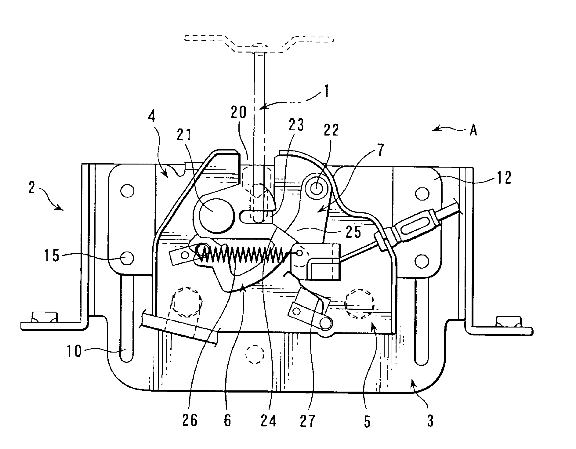
[0011]Accordingly, the present invention is conceived as a response to the above-described disadvantage of the conventional art, and has as an object to provide a retractable roof fixing apparatus that can snugly draw the roof to a vehicle body and fix the roof to the body by greatly retracting a striker.
[0012]Another object of the present invention is to provide a retractable roof fixing apparatus that securely draws the roof to a vehicle body and fixes the roof to the body by driving a motor that rotates a cam that greatly retracts a striker engaging a latch.
[0013]According to the retractable roof fixing apparatus described above, the retractable roof fixing apparatus can limit an increase in load on the motor even when a lifting force applied from the roof to the latch approaches a retraction limit position.

Problems solved by technology

If left exposed when not in use, however, the roof not only impedes the rear view of the operator of the vehicle but is also unsightly, susceptible to dust and dirt, and may experience color fading.
However, when fixing a retractable roof to the vehicle body, such minimal distances create a risk that vibration during operation of the vehicle might open a gap between the roof and the body.

Method used


Image

  • Retractable roof fixing apparatus
  • Retractable roof fixing apparatus
  • Retractable roof fixing apparatus

Examples


second embodiment

[0102]A description is now given of the present invention.

[0103]It should be noted that the basic structure and function of the second embodiment are identical to those of the first embodiment described above, and therefore a description thereof is omitted here.

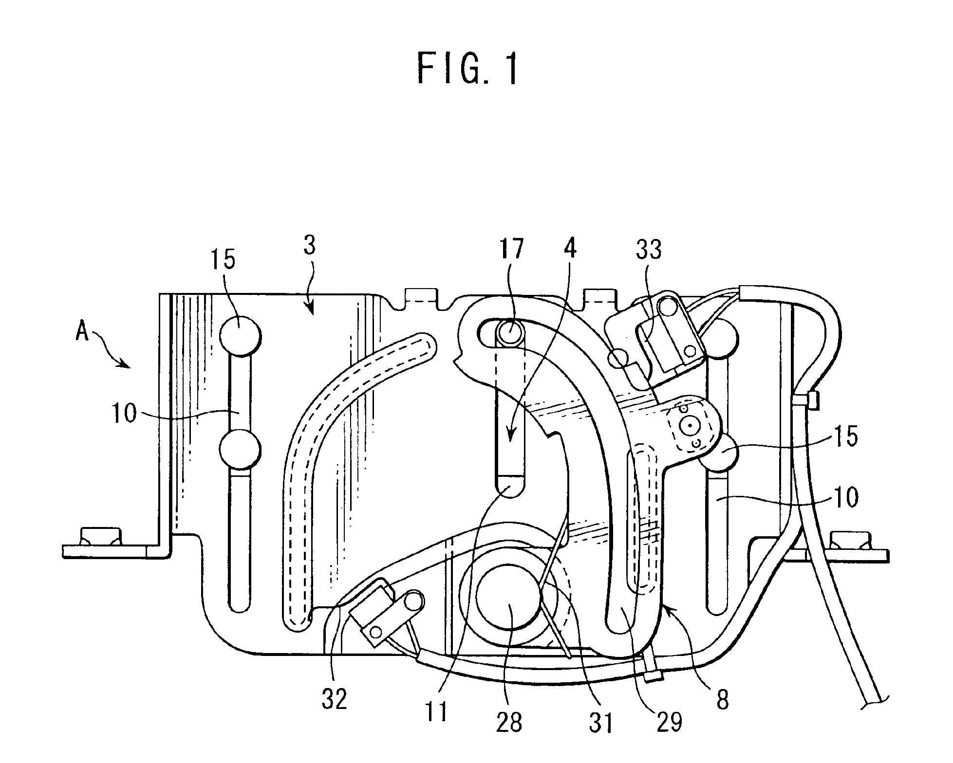
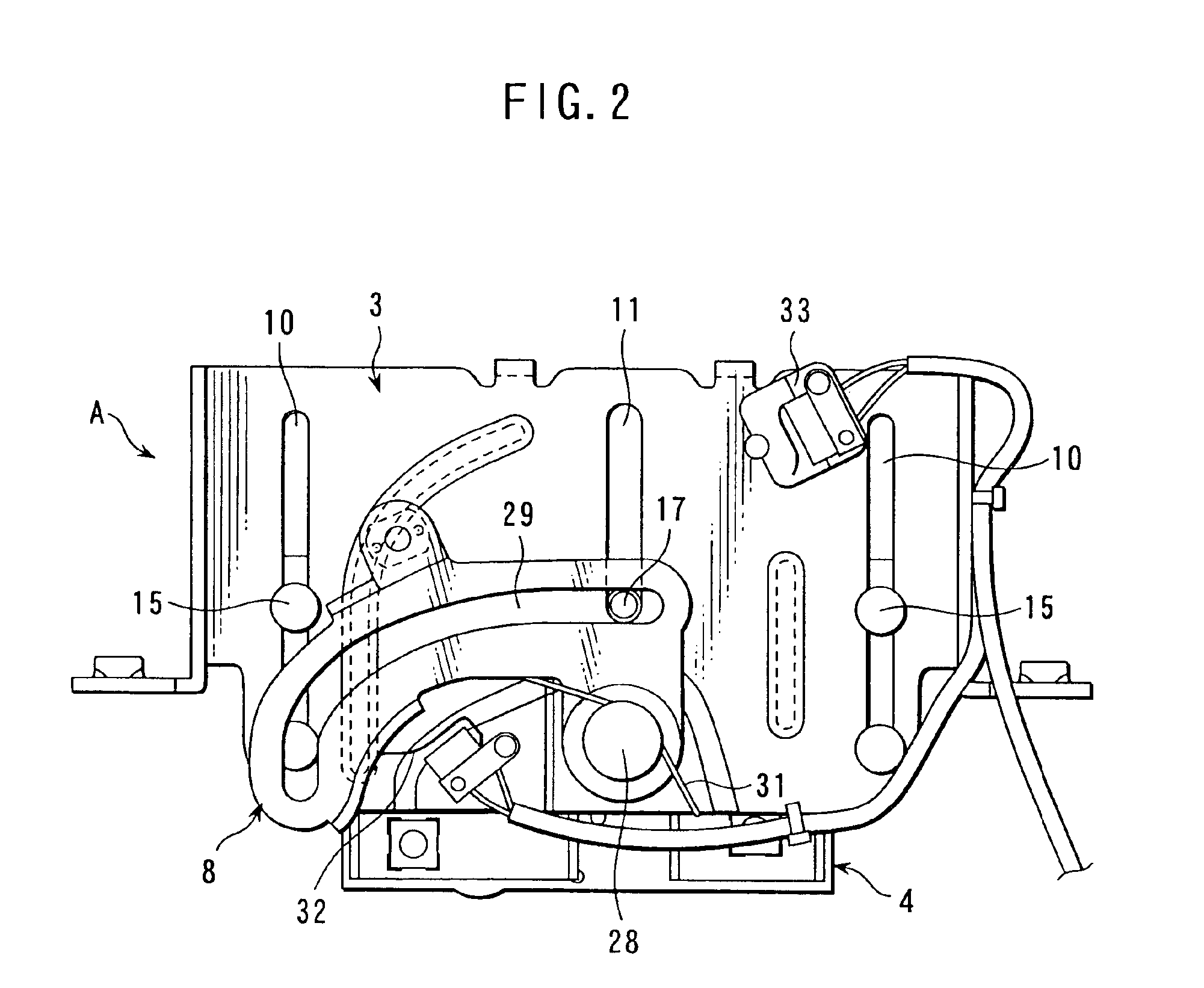
[0104]According to the second embodiment of the present invention, a slide projection is provided on the slide plate, the slide projection engages the cam, the cam has a cam slot that slides the slide projection in the direction of movement of the striker with a rotation of the cam, and the cam slot has a shape that gradually decreases retraction when the slide projection approaches a retraction limit position.

[0105]One end of the cam slot 29 (that is, the end near the third shaft 28) is substantially straight over a comparatively long distance, with the other end formed straight over a shorter distance and an intermediate portion curved in approximately an arc. When the slide projection 17 engages either end of the cam slot ...


PUM


Abstract

A retractable roof fixing apparatus capable of drawing the roof to a vehicle body to be snugly fixed thereto by automatically retracting a striker engaged with a latch by a sufficient distance. The retractable roof fixing apparatus comprises: a striker fixed on a roof; a base plate fixed on a body of a vehicle; a slide plate slidably attached to the base plate in a direction of movement of the striker; a latch rotatably mounted on the slide plate that engages the striker with a rotation of the latch; a cam rotatably mounted on the base plate; and a motor that rotates the cam, wherein the motor operates when the striker engages the latch to rotate the cam so as to slide the slide plate away from the roof.

Description

CLAIM OF PRIORITY[0001]This application claims priority from Japanese Patent Application Nos. 2003-186932, 2003-187608, 2003-187789, 2003-187560 and 2003-187936, each titled “Retractable Roof Fixing Apparatus” and filed on Jun. 30, 2003, the entire contents of which are incorporated herein by reference.BACKGROUND OF THE INVENTION[0002]1. Field of the Invention[0003]The present invention relates to roof fixing apparatus, and more particularly, to a roof fixing apparatus for fixing a retractable roof provided on a convertible automotive vehicle.[0004]2. Description of Related Art[0005]Conventionally, a convertible automotive vehicle is provided with a retractable roof to cover the interior of the vehicle, so as to provide protection against cold weather and rain. Typically, such a retractable roof is mounted at a base to a rear part of the body of the vehicle, with a front end of the roof moved to extend and to retract the roof. If left exposed when not in use, however, the roof not o...

Claims


Application Information

Patent Timeline
IPC IPC(8): B60J7/185B60J7/00
CPCB60J7/185Y10S292/05
Inventor KUBOTA, JUNICHIYOSHIZAWA, MASAKANE
Owner JOHNAN SEISAKUSHO CO LTD
Learn More