
Grinding device for inner holes

Active Publication Date: 2022-05-12
LIAW JIAN SHIOU
View PDF0 Cites 0 Cited by
  • Summary
  • Abstract
  • Description
  • Claims
  • Application Information

AI Technical Summary

Benefits of technology

The present invention is a grinding device for inner holes that can be used to restrict the rotation of its extension shaft using a button assembly. The technical effect of this invention is to improve the stability and accuracy of inner hole grinding.

Problems solved by technology

However, in such operation, the user has both hands respectively holding the two wrenches, which means the user cannot hold the conventional grinding device with the user's hands.
To conclude, the nut of the conventional grinding device is not easy to be disassembled, and changing the tool fixed in the tool assembly is therefore a difficult task.

Method used


Image

  • Grinding device for inner holes
  • Grinding device for inner holes
  • Grinding device for inner holes

Examples


Embodiment Construction

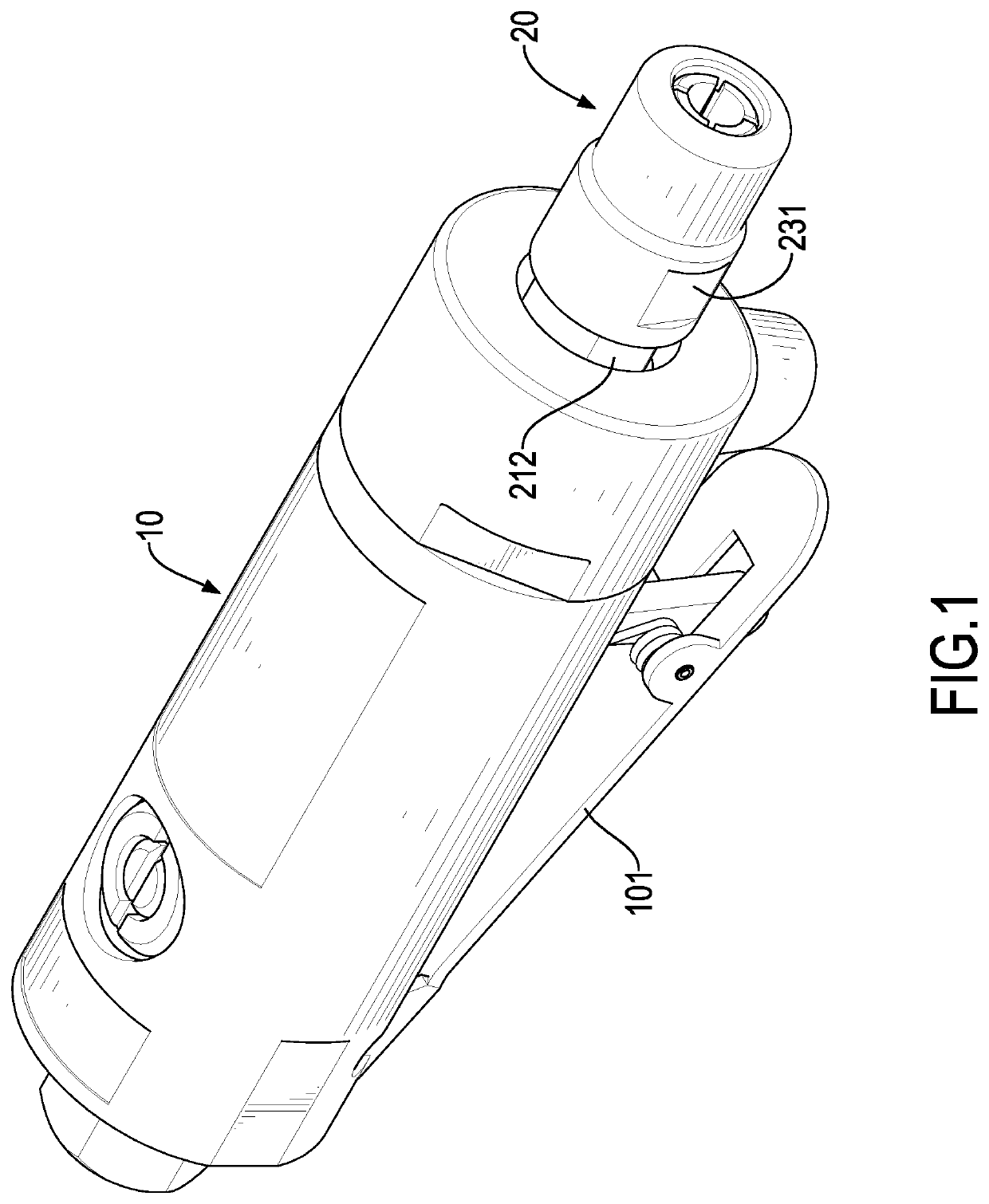
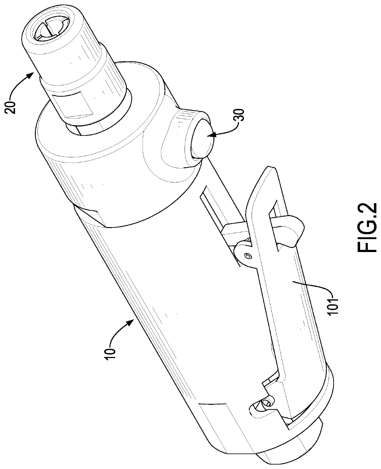
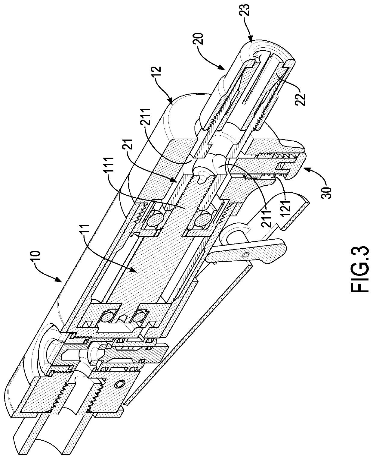
[0014]With reference to FIGS. 1 to 4, a grinding device for inner holes in accordance with the present invention has a body 10, a tool assembly 20, and a button assembly 30. The body 10 is formed substantially cylindrical, and is connected with a compressed air supply. The body 10 has a switch 101 and a pneumatic motor 11. The switch 101 is disposed on a side of the body 10. The pneumatic motor 11 is mounted in the body 10 and has a driving shaft 111. When a user presses the switch 101, gas under high pressure would be inlet into the body 10 via the compressed air supply, and the gas under high pressure may push the driving shaft 111 of the pneumatic motor 11 to rotate. Technical features of the switch 101 are same as those of the conventional grinding device, so detailed descriptions about the switch 101 are omitted.

[0015]Furthermore, the body 10 comprises an end cap 12 mounted on a front end of the body 10, so the pneumatic motor 11 may be kept in the body 10. The end cap 12 is a ...


PUM


Abstract

A grinding device for inner holes has a body, an extension shaft, a nut, and a button assembly. The body has a driving shaft rotatably disposed in the body and a containing hole disposed through a side of the body. The extension shaft has two ends and a concave structure. One of the two ends of the extension shaft is connected with the driving shaft of the body. The concave structure is disposed on the extension shaft, and is aligned with the containing hole of the body after the extension shaft rotates with the driving shaft. The nut is mounted on the other one of the two ends of the extension shaft. The button assembly is mounted in the containing hole of the body, and is able to be pressed and to extend into the concave structure to restrict the extension shaft from rotating.

Description

BACKGROUND OF THE INVENTION1. Field of the Invention[0001]The present invention relates to a grinding device, and more particularly to a grinding device for inner holes.2. Description of Related Art[0002]A conventional grinding device for inner holes comprises a body and a tool assembly. The body has a pneumatic motor disposed inside the body, and the pneumatic motor has a driving shaft. The tool assembly has an extension shaft, a collet, and a nut. The extension shaft is connected with the driving shaft of the pneumatic motor, and is thereby simultaneously rotatable with the driving shaft. The collet is mounted on an end of the extension shaft that is away from the driving shaft for installing a tool. The nut is mounted on the end of the extension shaft away from the driving shaft, so as to compress the collet and to stabilize the tool accordingly.[0003]In use, a wrench is necessary for assembling and disassembling the nut. To avoid the nut rotating along with the extension shaft d...

Claims


Application Information

Patent Timeline
IPC IPC(8): B24B23/02B24B47/10
CPCB24B23/02B24B47/10
Inventor LIAW, JIAN-SHIOU
Owner LIAW JIAN SHIOU
Learn More