Method and apparatus for determining the unbalance of a rotating body

Inactive Publication Date: 2004-08-24
SCHENCK ROTEC GMBH
View PDF13 Cites 24 Cited by
  • Summary
  • Abstract
  • Description
  • Claims
  • Application Information

AI Technical Summary

Benefits of technology

In the apparatus according to the invention, the plate-shaped dynamometer element receives or takes up all of the forces and moments that originate or are emitted from the rotational body, so that separate or additional supports and braces for the rotational body and for the mounting plate may advantageously be omitted. In the simplest manner, by embodying the pairs of supporting webs so that they not only support the axial thrust or weight forces, but also provide the vibrational or oscillating support of the mounting plate, it is possible to achieve an apparatus with an especially compact construction and particularly a low structural height. Moreover, the inventive apparatus has an essentially symmetrical construction with respect to the stiffness distribution as well as the mass distribution, and further achieves a very exact unbalance determination due to the improved plane separation.
The generally plate-shaped dynamometer element according to the invention may be fabricated in an especially economical manner, for example as an integral sheet metal part that is burned or cut out of a sheet metal plate and then formed as necessary, or as an integral cast part. The structure of the dynamometer element according to the invention makes it possible to achieve a very small spacing distance between the center of mass of the rotor and the reference plane of the dynamometer element. Ultimately, that leads to a more exact measurement result due to the improved separation of planes. The determination of the static unbalance is achieved very accurately, since the structure is essentially symmetrical and the measuring plane of the vibration transducer lies in the plane of the plate of the dynamometer element. The embodiment of the invention with only one vibration transducer is particularly advantageous for carrying out single plane unbalance measurements, and represents the simplest inventive structure.
The invention provides very simple measures for arranging the plate plane of the dynamometer element alternatively in the horizontal direction or the vertical direction. Thus, the inventive dynamometer element may be used in balancing machines that are adapted to special requirements, with vertical or horizontal rotation axes, in a very simple manner.
If the rotation axis is oriented in the vertical direction, whereby the plate plane extends in the horizontal plane, this advantageously provides a free space below the dynamometer element that is free and clear of separate supporting elements. Thus, the resulting free space beneath the dynamometer element can easily be used to accommodate other elements of a balancing machine or an unbalance measuring machine, for example the drive and control arrangements or clamping devices for securing the rotational body onto a balancing spindle or onto the mounting surfaces of the mounting plate. Overall, this leads to a compact, user-friendly, and service-friendly construction.
The above stated objects have further been achieved according to the invention in a method for determining the unbalance of a rotational body, using a plate-shaped dynamometer element including a mounting fixture for receiving the rotational body. According to the inventive method, the unbalance induced vibrations of portions of the dynamometer element are separately detectable or can be picked-up as translational vibrations and as pivotal vibrations. Further, particularly according to the invention, all of the forces and moments originating and emanating from the rotational body are transmitted into and through the dynamometer element. As mentioned above, this avoids the need for additional separate supports.

Problems solved by technology

On the other hand, the unbalance component arising from a single or individual force, namely a static unbalance, is detected or picked up by a further vibration transducer, of which the effective measuring direction extends parallel to the plane of the plate.
Such forces could influence the vibrating motions of the mounting plate and thereby correspondingly influence the accuracy of the unbalance determination in an undesirable manner.
Moreover, the inventive apparatus has an essentially symmetrical construction with respect to the stiffness distribution as well as the mass distribution, and further achieves a very exact unbalance determination due to the improved plane separation.

Method used


Image

  • Method and apparatus for determining the unbalance of a rotating body
  • Method and apparatus for determining the unbalance of a rotating body
  • Method and apparatus for determining the unbalance of a rotating body

Examples


Embodiment Construction

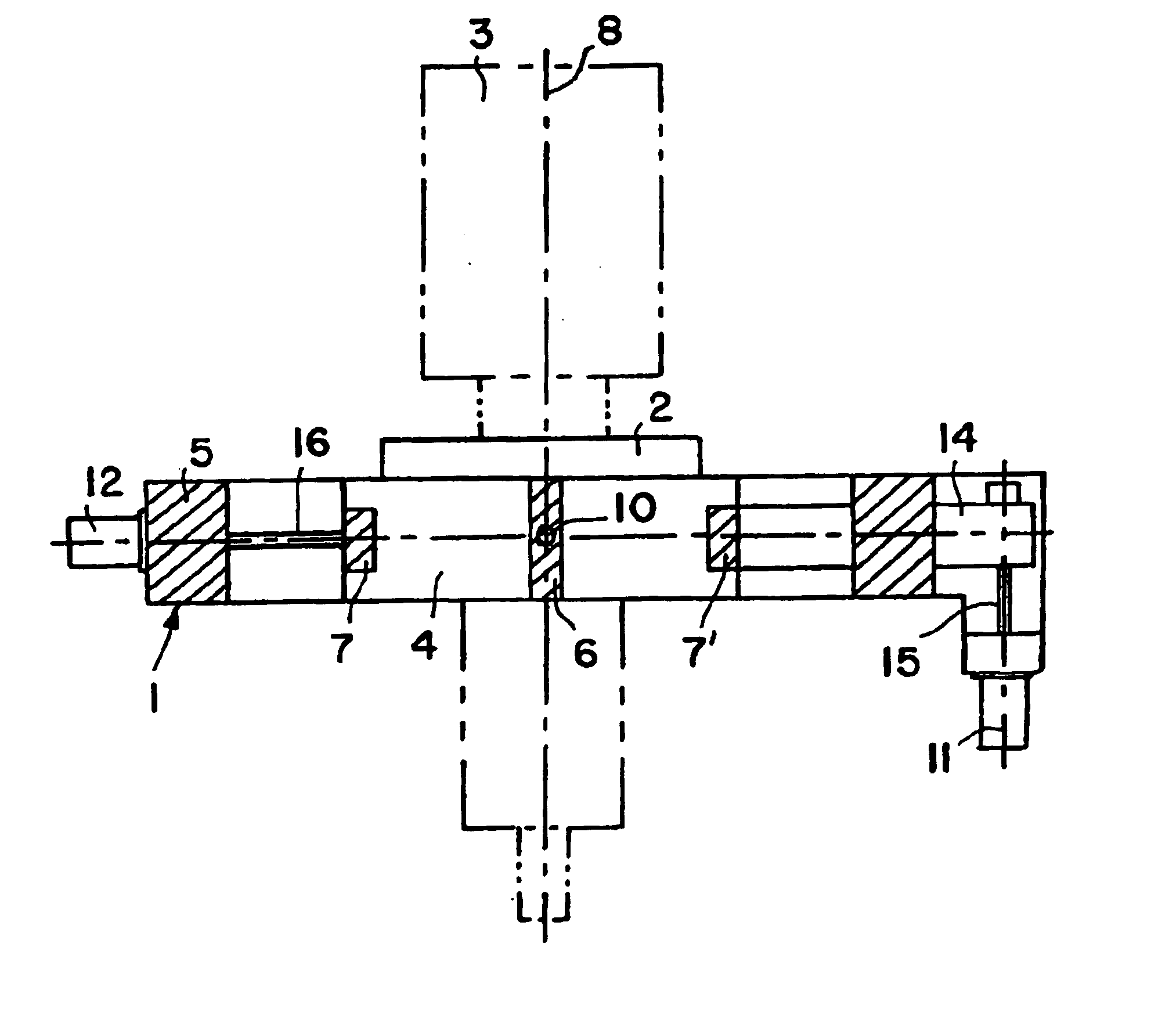
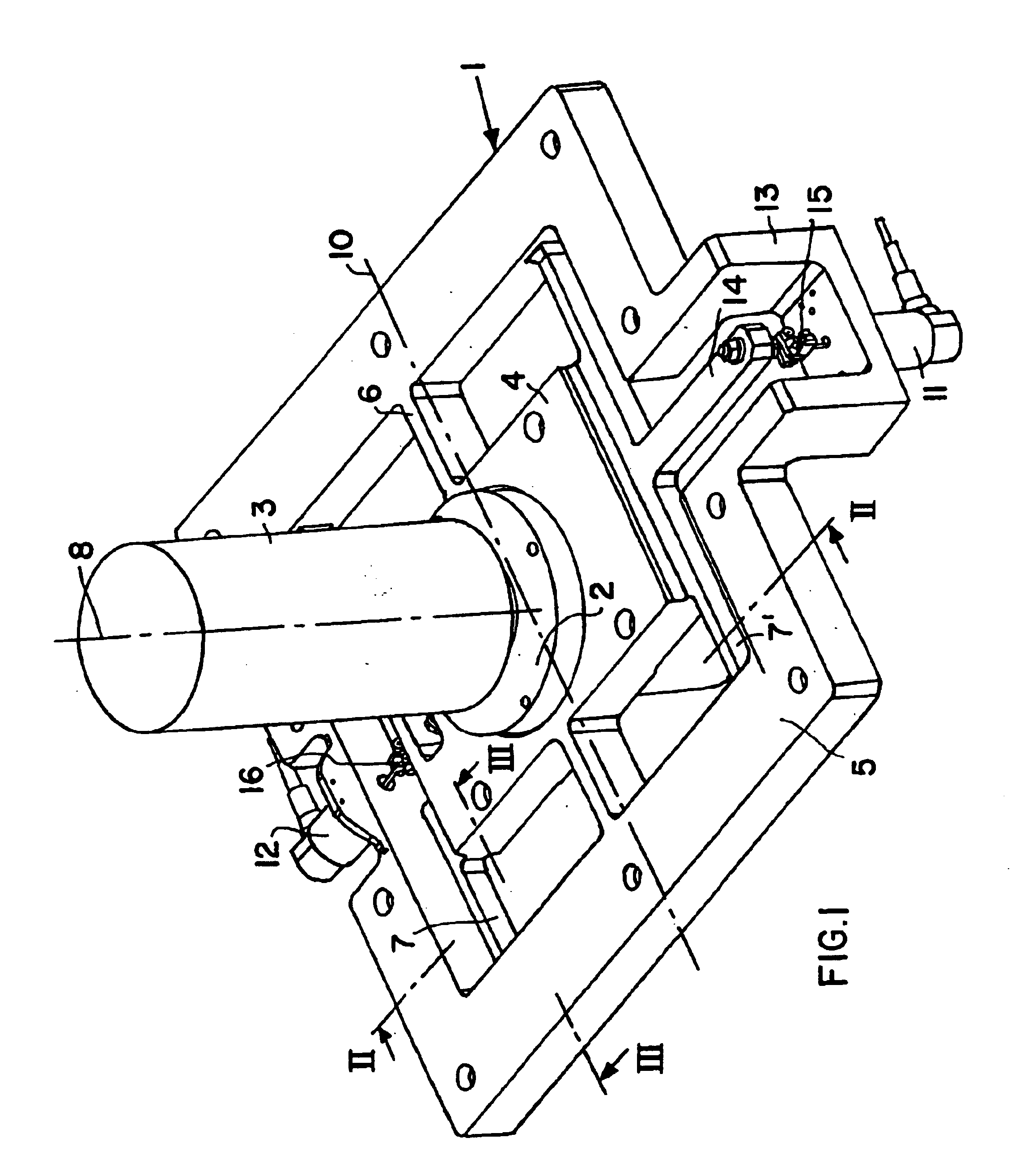
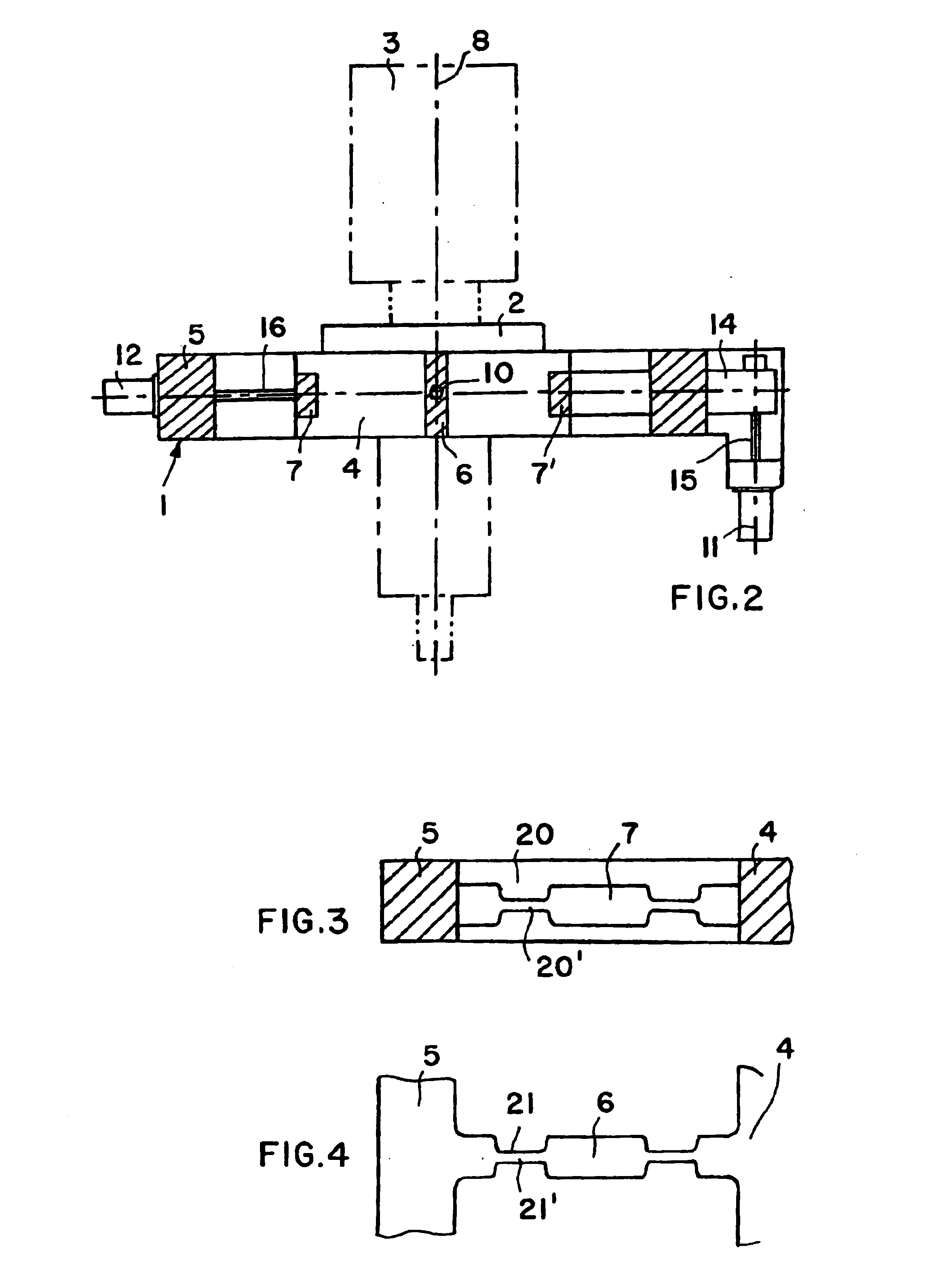
As shown in FIG. 1, the dynamometer element 1 of a balancing machine (which is not shown overall) comprises an inner mounting plate 4 and an outer frame 5, which are connected to each other by web pairs 6, 7, and 7'. The mounting plate 4 includes a mounting fixture 2 adapted to receive a rotational body 3 thereon, whereby this rotational body is to be rotated about a rotation axis 8, in order to measure the unbalance of the rotational body 3 using the dynamometer element 1. The terms "dynamometer" and "dynamometer element" as used herein refer to a spring-suspended supporting and measuring system as generally understood in the field of balancing technology.

The mounting fixture 2 is received in a bore in the mounting plate 4, and may comprise a plurality of mounting surfaces on which the rotational body 3 is secured, as shown in the illustrated example. Alternatively, or further, the mounting fixture 2 may comprise a balancing spindle, for example, on which the rotational body 3 that...


PUM


Abstract

An apparatus for determining the unbalance of a rotational body includes a central mounting plate with a mounting fixture on which the rotational body is received, an outer frame, and a plurality of supporting webs that connect the mounting plate to the frame. The webs are configured and arranged so that the mounting plate can pivotally vibrate about a pivot axis, and translationally vibrate in the plane of the mounting plate. A first vibration transducer measures the pivoting vibration and a second vibration transducer measures the translational vibration. The pivot axis remains in the central plane of the mounting plate which coincides with the effective plane of the translational vibration measuring transducer. In this manner, the translational vibration induced by a static unbalance, and the pivoting vibration induced by the moment unbalance are separated and then separately measured, which enables the accurate measurement of both the static unbalance component and the moment unbalance component of a dynamic unbalance. In a method using such an apparatus, all of the forces and moments originating from the rotational body are transmitted directly into and through the dynamometer element itself, without requiring any additional supporting elements.

Description

PRIORITY CLAIMThis application is based on and claims the priority under 35 U.S.C. .sctn.119 of German Patent Application 199 37 495.3, filed on Aug. 7, 1999, the entire disclosure of which is incorporated herein by reference.The invention relates to a method and an apparatus for determining the imbalance or unbalance of a rotating body that is mounted on a generally plate-shaped dynamometer element extending on a plane perpendicular to the rotation axis. The dynamometer element includes an inner mounting plate connected by webs to an outer frame, and at least one vibration transducer arranged between the plate and the frame for picking up unbalance induced vibrations of the mounting plate relative to the frame. The unbalance of the rotating body induces vibrations that can be detected separately as translational vibrations and pivotal vibrations.BACKGROUND INFORMATIONGerman Patent Laying-Open Publication 28 47 295 discloses a balancing machine comprising a plate-shaped dynamometer ...

Claims


Application Information

Patent Timeline
IPC IPC(8): G01L5/16G01M1/00G01M1/04G01M1/22G01H17/00
CPCG01L5/16G01M1/04
Inventor THELEN, DIETERSTORK, MICHAEL
Owner SCHENCK ROTEC GMBH
Why Eureka
Try Eureka