Eureka AIR delivers breakthrough ideas for toughest innovation challenges, trusted by R&D personnel around the world.

Ultraviolet treatment for aqueous liquids

Inactive Publication Date: 2004-08-10
UV PURE TECH
View PDF28 Cites 80 Cited by
  • Summary
  • Abstract
  • Description
  • Claims
  • Application Information

AI Technical Summary

Benefits of technology

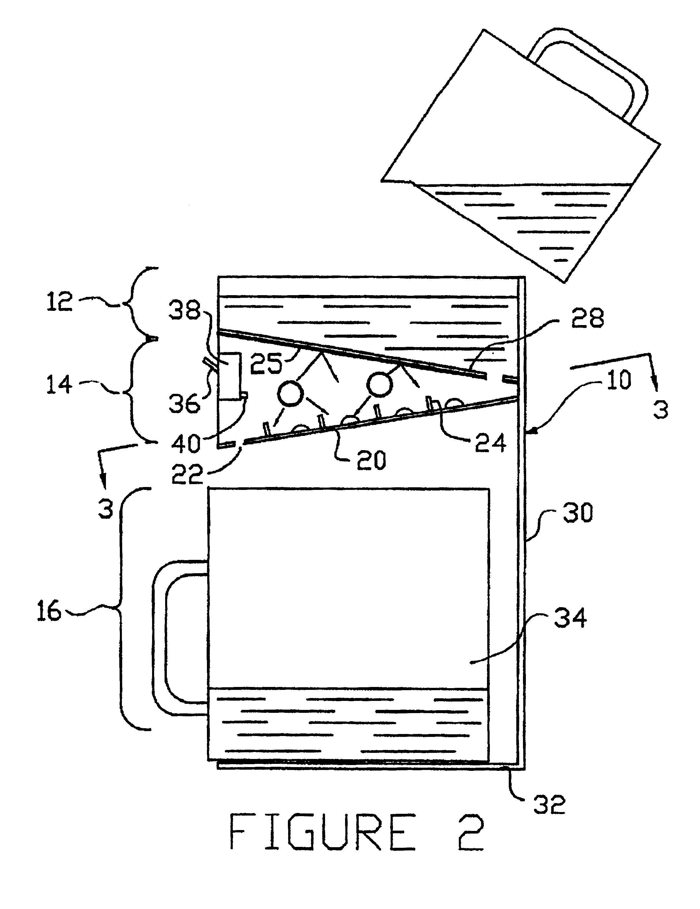
In a preferred approach, disrupting the flow of liquid involves passing the liquid under the force of gravity down a trough in the treatment area, the trough being shaped to provide physical barriers which purposefully obstruct the even flow of liquid flowing through the trough. The main purpose of the obstructions is to force portions of the liquid resident at the bottom of the trough upwardly toward the surface of the liquid. This brings a greater proportion of the contents of the liquid into close contact with the UV light rays and thus increases the effectiveness of the action of the UV light on the liquid.
The second sensor can be trained to receive light rays that form an angle of between 0.degree. and about 150.degree. with light rays emitted from the lamp. The angle might be between 0.degree. and about 120.degree., between about 45.degree. and about 120.degree., or between about 80.degree. and about 100.degree.. In the disclosed embodiment, the angle is about 90.degree., but it might be possible to improve performance by changing this angle.
The greater the degree of reflectance from the reflective surfaces, the more effective the treatment. This is because the reflected rays make there way back into the liquid being treated and thus increase the dosage of the UV rays being applied to the liquid. This is more the case when the liquid itself is highly translucent. Preferably, the reflective surfaces reflect at least 25% of UV light emitted from the lamp in the absence of liquid; better yet, the reflective surfaces reflect at least 40% of UV light emitted from the lamp in the absence of liquid; better still, the reflective surfaces reflect at least 90% or even 95% or more of UV light emitted from the lamp in the absence of liquid.

Problems solved by technology

If the lines are not distinct, then the liquid is too turbid to be suitable for treatment.

Method used


Image

  • Ultraviolet treatment for aqueous liquids
  • Ultraviolet treatment for aqueous liquids
  • Ultraviolet treatment for aqueous liquids

Examples


examples

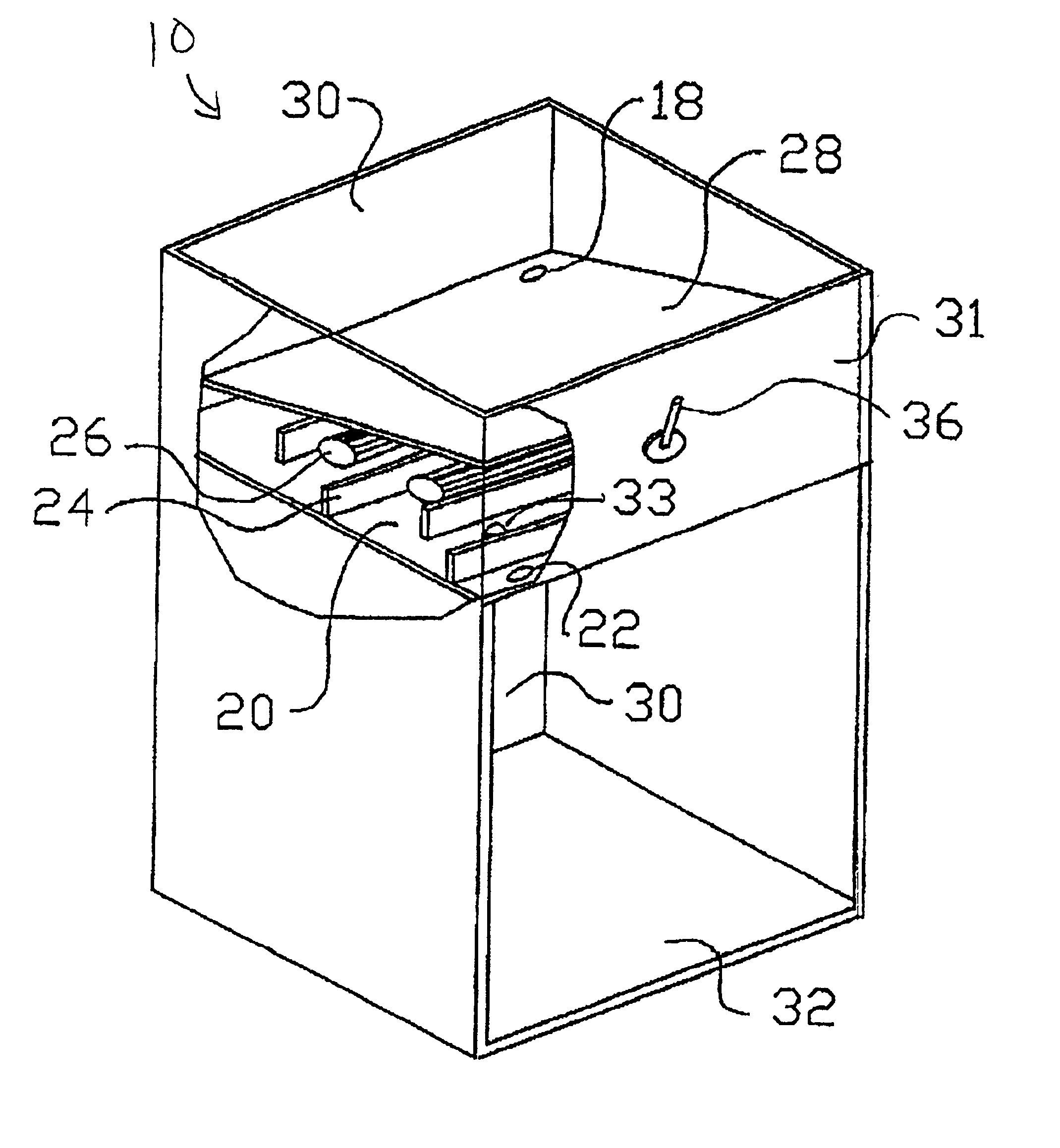
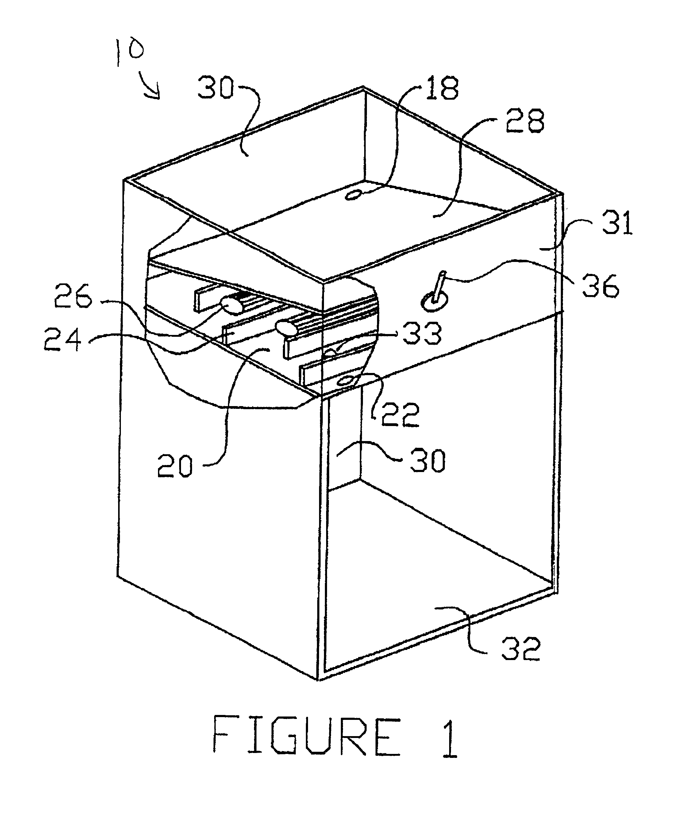
In a first trial, an apparatus similar to that illustrated in FIG. 1 was used, but in this case, there were no protrusions in the troughs (channels) of the apparatus. Distilled water was spiked with Bacillus subtilis spores to give a count of 39,000 CFU's (colony forming units) per ml. The water was poured through the apparatus at a rate of 800 ml / min. The effluent (liquid emerging from the treatment area of the apparatus) had a spore count of 2,200 CFU's per ml. In a comparative run, the same experiment was carried out using the apparatus as illustrated in FIG. 1, that is, four evenly spaced semi-circular protrusions (the protrusions were 0.5 cm in height in these examples) were located in the centre of each channel. In this case, the effluent had a spore count of 330 CFU's per ml.

In a second trial, deionized water was spiked with Crypto sporidium parvum to a concentration of 10,000 per ml. The water was poured through the apparatus illustrated in FIG. 1, again at a rate of about 8...


PUM

PropertyMeasurementUnit
Fractionaaaaaaaaaa
Fractionaaaaaaaaaa
Thicknessaaaaaaaaaa

Abstract

A process for treating an aqueous liquid. The process includes: passing the liquid by force of gravity through a treatment area, the liquid having an upper surface exposed to ambient pressure; disrupting the flow of the liquid as it passes through the treatment area, and exposing the upper surface of the liquid as the flow is disrupted to UV light. Disrupting the flow includes directing lower portions of the liquid toward the surface of the liquid to bring such portions into contact with UV light. A process for treating an aqueous liquid in which the treatment process is monitored. This process includes passing the liquid through a treatment area to bring the liquid into contact with reflective walls submerged below an upper surface of the liquid, and exposing the upper surface of the liquid to light emitted from a UV light source such that UV light penetrates the liquid to strike the submerged reflective surfaces and to be reflected therefrom to emerge through the upper surface of the liquid. The process also involves determining the intensity of the UV light emitted from the light source, determining the intensity of UV light received by a UV light sensor trained to receive emergent light and determining whether the treatment has a predetermined effectiveness based on the intensity of the UV light emitted from the light source and the intensity of the UV light received by the sensor. Apparatuses for carrying out processes of the invention are also described.

Description

The present invention is directed to an ultraviolet (UV) treatment for aqueous liquids such as water or biological fluids.BACKGROUND OF INVENTIONThere are many approaches to treating aqueous liquids. The approach taken depends upon a number of factors including the nature of the liquid, the object of the treatment, and the site of treatment, among other factors.In the case of water to be used for human consumption, the object of treatment might be: to remove certain toxins, such as halogenated hydrocarbons or lead; to reduce the pathogenic content, e.g., render bacteria or viruses less virulent; or to remove components that detract from the taste or smell, but which are otherwise relatively harmless. The site of treatment might be a communal source such as a municipal water treatment plant, or it could be at the point of use, such as in the home.The present invention involves the use of UV radiation in treatment of aqueous liquids. When the liquid is drinking water, for example, an ...

Claims


Application Information

Patent Timeline
IPC IPC(8): A61L2/00A61L2/28A61L2/26A61L2/10B01J19/12C02F9/00C02F1/32
CPCA61L2/0011A61L2/10A61L2/28B01J19/123C02F1/325C02F9/005B01J2219/00164B01J2219/0801B01J2219/0877C02F2201/009C02F2201/3221C02F2201/3227C02F2201/3228C02F2201/326Y02W10/37A61L2/0047Y02A20/212C02F9/20
Inventor HALLETT, RONALD C.HALLETT, DOUGLAS J.
Owner UV PURE TECH
Why Eureka
Eureka Blog
Learn More