Headrest apparatus for vehicle
- Summary
- Abstract
- Description
- Claims
- Application Information
AI Technical Summary
Benefits of technology
Problems solved by technology
Method used
Image

Examples
first embodiment
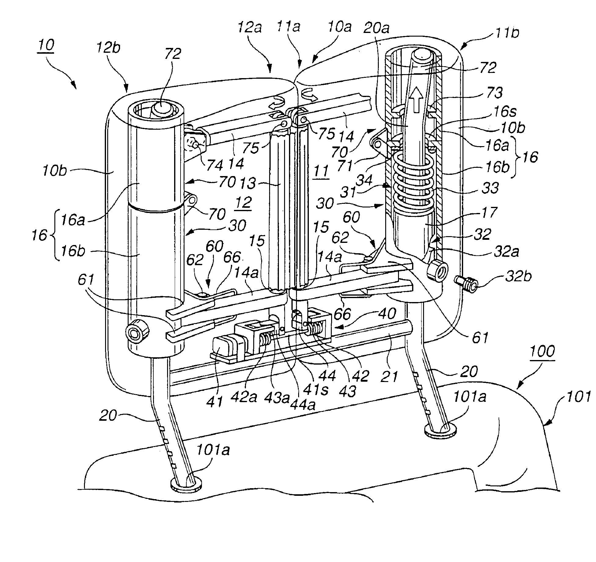
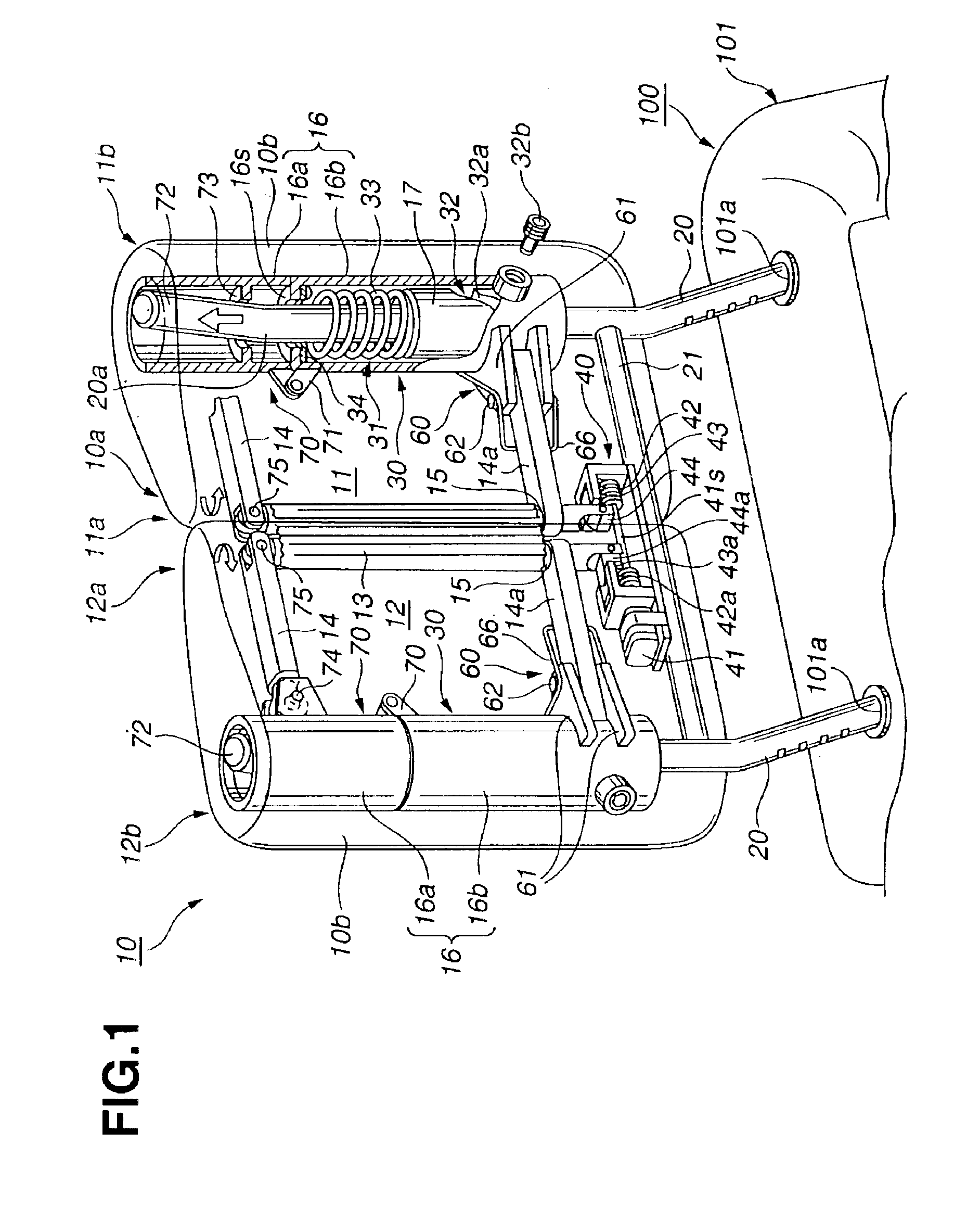
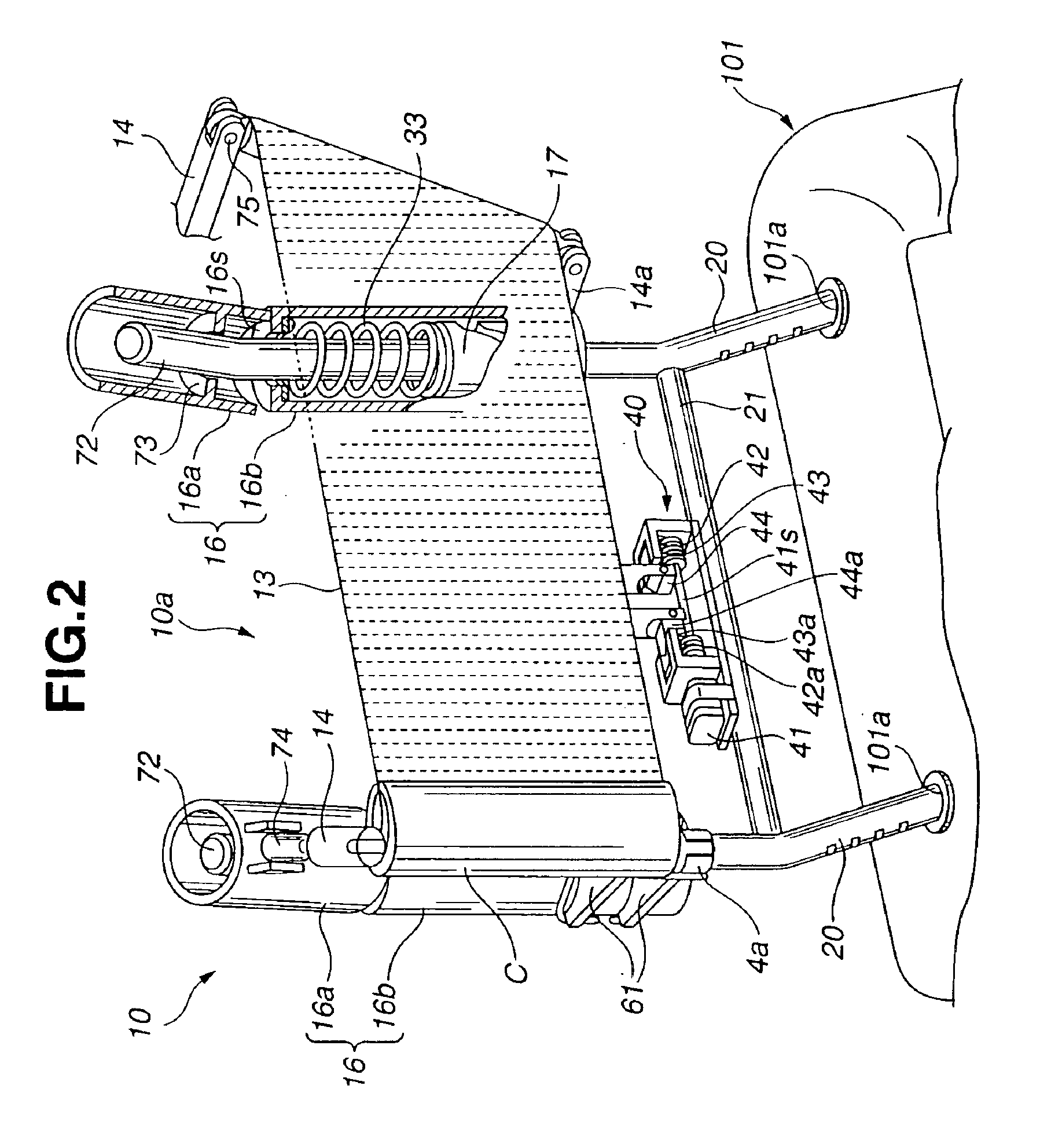
[0026]FIGS. 1˜9 show a headrest apparatus 10 according to the present invention.
[0027]As shown in FIGS. 1˜3, headrest apparatus 10 is to be mounted on an uppermost portion of a seatback 101 of a seat 100 for a vehicle. Headrest apparatus 10 includes a headrest member (main member) 10a for supporting the head of a seat occupant. Headrest member 10a is mounted on seatback 101 through left and right mount members (guide members) 20 including lower segments inserted, respectively, into left and right mounting holes 110a formed in seatback 101. Each of left and right mount members 20 in this example is in the form of a stay or rod extending vertically or upwards from the uppermost portion of seatback 101 in the assembled state shown in FIG. 1. In this example, left and right stays 20 support headrest member 10a so that the position of headrest member 10a can be adjusted vertically.
[0028]A cross bar 21 extends in a left and right direction (the lateral direction of the vehicle) between le...
third embodiment
[0073]FIGS. 11 and 12 (12A and 12B) show a main portion of a headrest apparatus according to the present invention. The third embodiment is different from the first embodiment in the following points. In the other respects, the third embodiment is substantially identical to the first embodiment. Corresponding parts are given the same reference numerals, and repetitive explanation is omitted. In the third embodiment, the connecting member connecting upper and lower pieces 16a and 16b is a set of connecting springs 77, instead of hinge 71 of the first embodiment. In the state of FIG. 11, each of connecting springs 77 extends vertically along the center line or axis of outer cylinder 16. In the illustrated example, three upper hooks 77a are arranged regularly around the outer circumference of upper piece 16a near the lower end of upper piece 16a, and projected outward. Similarly, three lower hooks 77b are arranged regularly around the outer circumference of lower piece 16b near the upp...
fourth embodiment
[0076]FIGS. 13 and 14 (14A and 14B) show a main portion of a headrest apparatus according to the present invention. The fourth embodiment is different from the third embodiment in the following points. In the other respects, the fourth embodiment is substantially identical to the third embodiment. Corresponding parts are given the same reference numerals, and repetitive explanation is omitted. In the fourth embodiment, the connecting member connecting upper and lower pieces 16a and 16b is an elastomeric member 78. Elastomeric member 78 of this example is annular, or in the form of a hollow cylinder having a diameter substantially equal to the diameter of upper and lower cylindrical pieces 16a and 16b. An upper end of elastomeric member 78 is bonded by vulcanization to the lower end of upper piece 16a, and a lower end of elastomeric member 78 is bonded by vulcanization to the upper end of lower unit 16b.
[0077]When outer cylinder 16 is moved upward, upper piece 16a slides upward alon...
PUM
 Abstract
Description
Claims
Application Information
 - R&D
- Intellectual Property
- Life Sciences
- Materials
- Tech Scout
- Unparalleled Data Quality
- Higher Quality Content
- 60% Fewer Hallucinations
Browse by: Latest US Patents, China's latest patents, Technical Efficacy Thesaurus, Application Domain, Technology Topic, Popular Technical Reports.
© 2025 PatSnap. All rights reserved.Legal|Privacy policy|Modern Slavery Act Transparency Statement|Sitemap|About US| Contact US: help@patsnap.com