
Light display panel control

a technology of illuminated panels and control panels, applied in the direction of display means, instruments, static indicating devices, etc., can solve the problems of aging in these diodes, drifting etc., and achieve the effect of preventing or at least reducing any drift in the colors of the illuminated panels over tim

Inactive Publication Date: 2004-06-29
DECAUX JEAN CLAUDE
View PDF6 Cites 129 Cited by
  • Summary
  • Abstract
  • Description
  • Claims
  • Application Information

AI Technical Summary

Benefits of technology

To this end, the invention proposes an illuminated display panel of the type in question essentially characterized in that the electronic control system is set up to vary the reference electrical power Pr specific to the light elements of each color over time, in accordance with a different predetermined variation depending on the colors, in order to compensate, at least partially, for the effects of aging of the light elements.
As a result of these features, any drift in the colors of the illuminated panel over time is prevented or at least reduced.

Problems solved by technology

However, the light elements are generally provided in the form of electroluminescent diodes of differing technologies depending on the colors, which means that aging in these diodes differs from one color to another.
This results in a drift in the colors of the illuminated panel over a period of time.

Method used


Image

  • Light display panel control
  • Light display panel control

Examples


Embodiment Construction

The same reference numbers are used in the different drawings to denote the same or similar elements.

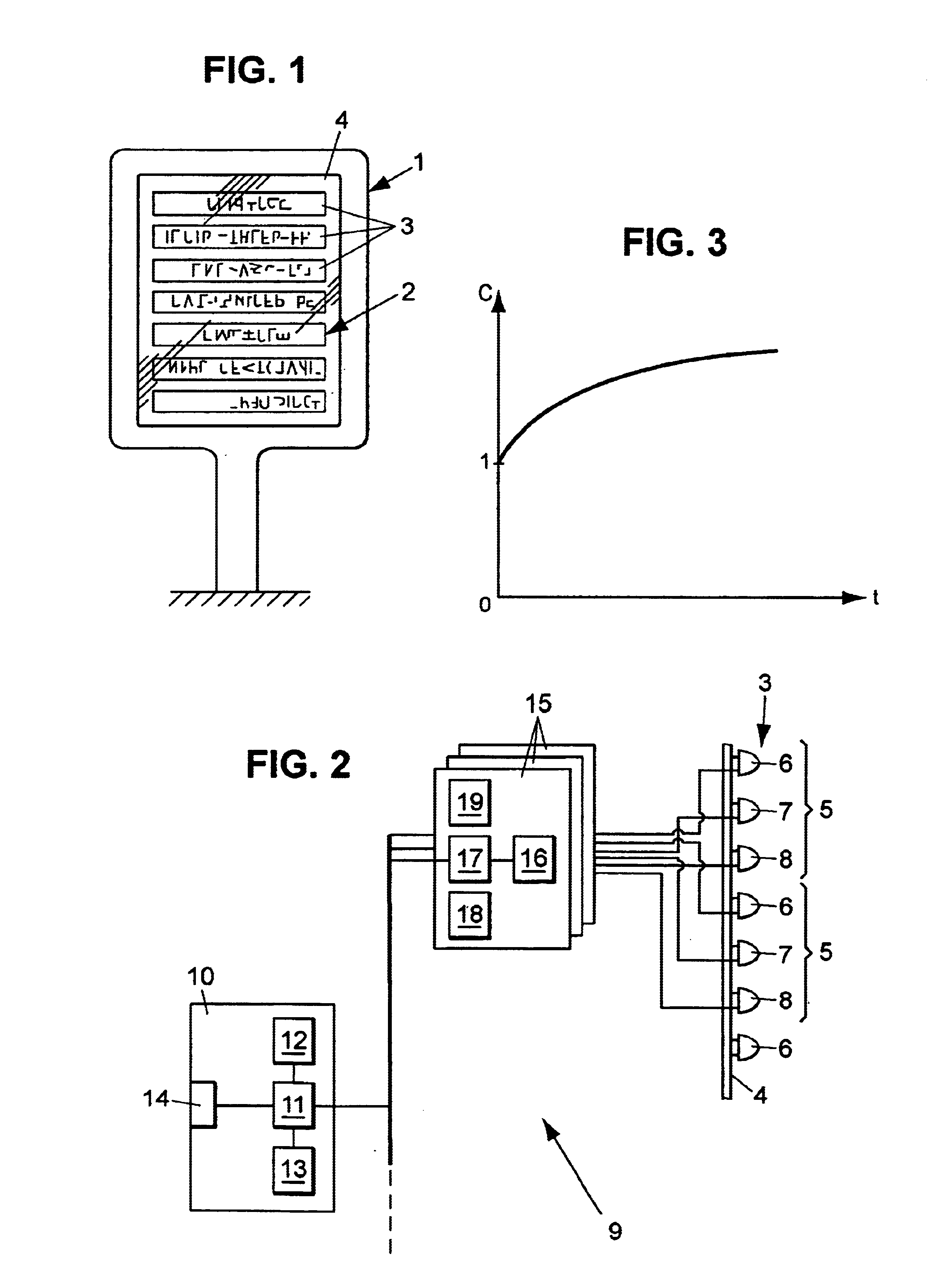
FIG. 1 illustrates an example of an illuminated color display panel 1 as proposed by the invention, which might be installed in a city area to broadcast advertising information to users of the public highway.

The display panel 1 comprises a transparent front face 2, covering matrices 3 of light elements disposed on an opaque background 4.

Depending on the circumstances, the display panel might have only one matrix 3 of light elements, extending substantially across the entire front face of the panel.

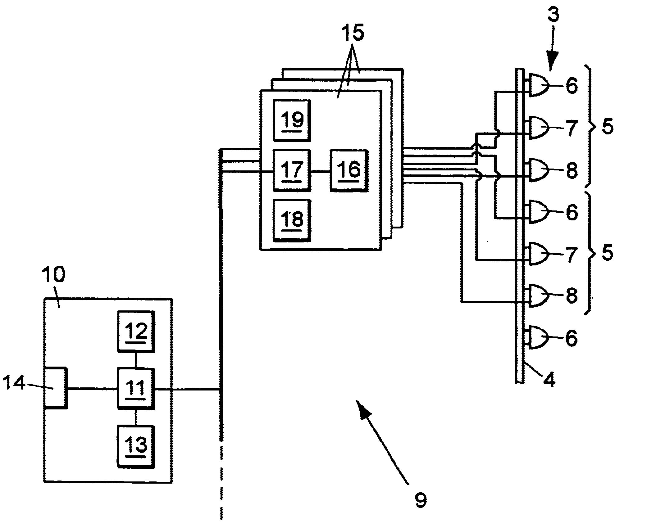
As schematically illustrated in FIG. 2, each matrix 3 of light elements is made up of a large number of pixels 5 or illuminated dots, of small dimensions, each pixel 5 comprising three electroluminescent diodes 6, 7, 8 of three different colors, for example red, green blue. Optionally, each pixel may comprise more than three diodes, for example several diodes mounted in series for each of t...


PUM


Abstract

The disclosure concerns a light display panel with a matrix of pixels each comprising three monochrome electroluminescent diodes of three colors. The diodes are controlled by a control circuit delivering electrical power P to each diode, said electrical power being expressed in the form P-k.Pr, wherein Pr is a reference electrical power particular to the diodes of each color and k is a coefficient selected according to the display to be presented. Over the course of time the reference electrical power is subjected to different variations depending on the colors, to compensate for the aging of the diodes.

Description

FIELD OF THE DISCLOSUREThe present invention relates to illuminated display panels.BACKGROUND OF THE DISCLOSUREMore specifically, the invention relates to an illuminated display panel having at least one matrix of light pixels, each pixel comprising at least three monochrome electric light elements emitting light respectively in at least three complementary colors, operation of the light elements being controlled by an electronic control system which determines an electrical power P applied to each light element, this electrical power being expressed in the form of P=k.Pr, where:Pr is a reference electrical power specific to the light elements of each colorand k is a real number at least equal to 0, selected as a function of the display to be presented on the panel.Known display panels of this type enable illuminated displays to be presented in color.However, the light elements are generally provided in the form of electroluminescent diodes of differing technologies depending on the...

Claims


Application Information

Patent Timeline
Patent Type & Authority Patents(United States)
IPC IPC(8): G09F15/00G09G3/32G09F9/33G09G3/30G09G3/12
CPCG09G3/12G09G3/32G09G2320/043
Inventor DECAUX, JEAN-CLAUDELE GARS, JACQUES
Owner DECAUX JEAN CLAUDE
Learn More