
Multi protocol label switching for multiple access segments

a multi-protocol label and access segment technology, applied in the field of multi-protocol label switching for multiple access segments, can solve the problems of large and complex routing tables, occupying a lot of space, and a scarce resource of space, so as to reduce the number of labels used, reduce the size of labels, and less space

Inactive Publication Date: 2004-05-04
RPX CLEARINGHOUSE
View PDF11 Cites 65 Cited by
  • Summary
  • Abstract
  • Description
  • Claims
  • Application Information

AI Technical Summary

Benefits of technology

The object of the invention is to reduce the number of labels used in such MA segments in order to reduce the size of the labels so that they take up less space in each packet transmitted over the MA segment and to reduce the size and complexity of the routing table used by the switching node. A further object of the invention is to reduce the number of packets that have to be transmitted over the MA segment in order to distribute the labels so as to reduce the amount of signalling resource taken up by label distribution.
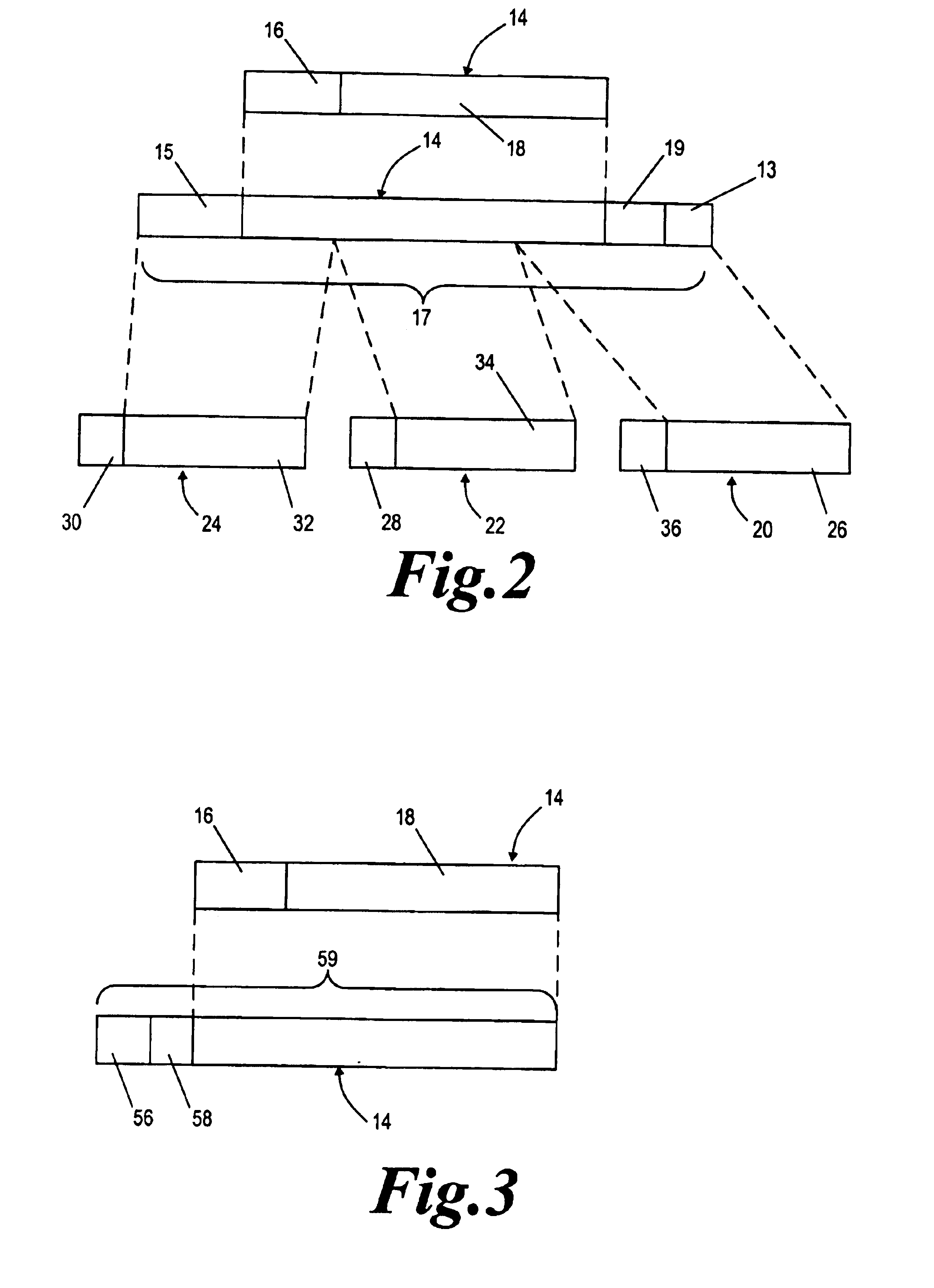
In this way the number of labels used for switching by the switching node is much reduced. This number is significantly less than in known systems which allocate separate labels to each end system, per intermediate destination and per QoS class. This means that less space in each packet header is used for the primary label and that the label routing information, usually in the form of a routing table, used by the switching node and communicated to the end systems is less complex than in known systems. Also, because the label routing information is independent of the end system from which a packet originates, the same label routing information can be sent to each end system. Thus, the switching node can send the same packets of label routing information to all the end systems which packets will be received by all the end systems. In previous systems different label routing information was sent to each end system and so many more packets had to be sent over the MA segment in order to provide all the end systems with label routing information. Accordingly, the present invention significantly reduces the amount of signalling resource within the MA segment which is used for distributing label routing information to the end systems.
As an alternative to, or in addition to, the switching node transmitting the primary label routing information, generally in the form of a routing table, to the end systems by broadcast or multicast, the end systems may comprise means for making on demand requests for primary labels from the switching node which requests set out the destination and the QoS required for a packet and the switching node comprises means for transmitting to all the end systems a set of label routing information including a mapping between the requested destination and QoS and the primary label. The set of label routing information sent may comprise the whole or a part of the label routing information for ad destination and QoS pairs. Because the set of information is received by all end systems, all the end systems will be able to use the set of information they receive to update their primary label routing information, thus reducing the number of on demand requests made by end systems across the MA segment which reduces the number of packets which have to transmitted across the MA segment in order to transmit the label routing information to all the end systems. This on-demand type of label distribution may be required if the broadcast or multicast is not totally reliable or if an end system becomes active just after the switching node has sent label routing information to all the end systems. Label routing information may be transmitted by the switching node at pre-determined time intervals or these transmissions may be event driven or driven by the network control policy for the communication system.

Problems solved by technology

These labels will necessarily be relatively long and will therefore take up a lot of space in the headers of the packets transmitted over the MA segment, which space is a scarce resource.
The large number of labels results in a large and complex routing table which has to be used by the switching node.

Method used


Image

  • Multi protocol label switching for multiple access segments
  • Multi protocol label switching for multiple access segments
  • Multi protocol label switching for multiple access segments

Examples


Embodiment Construction

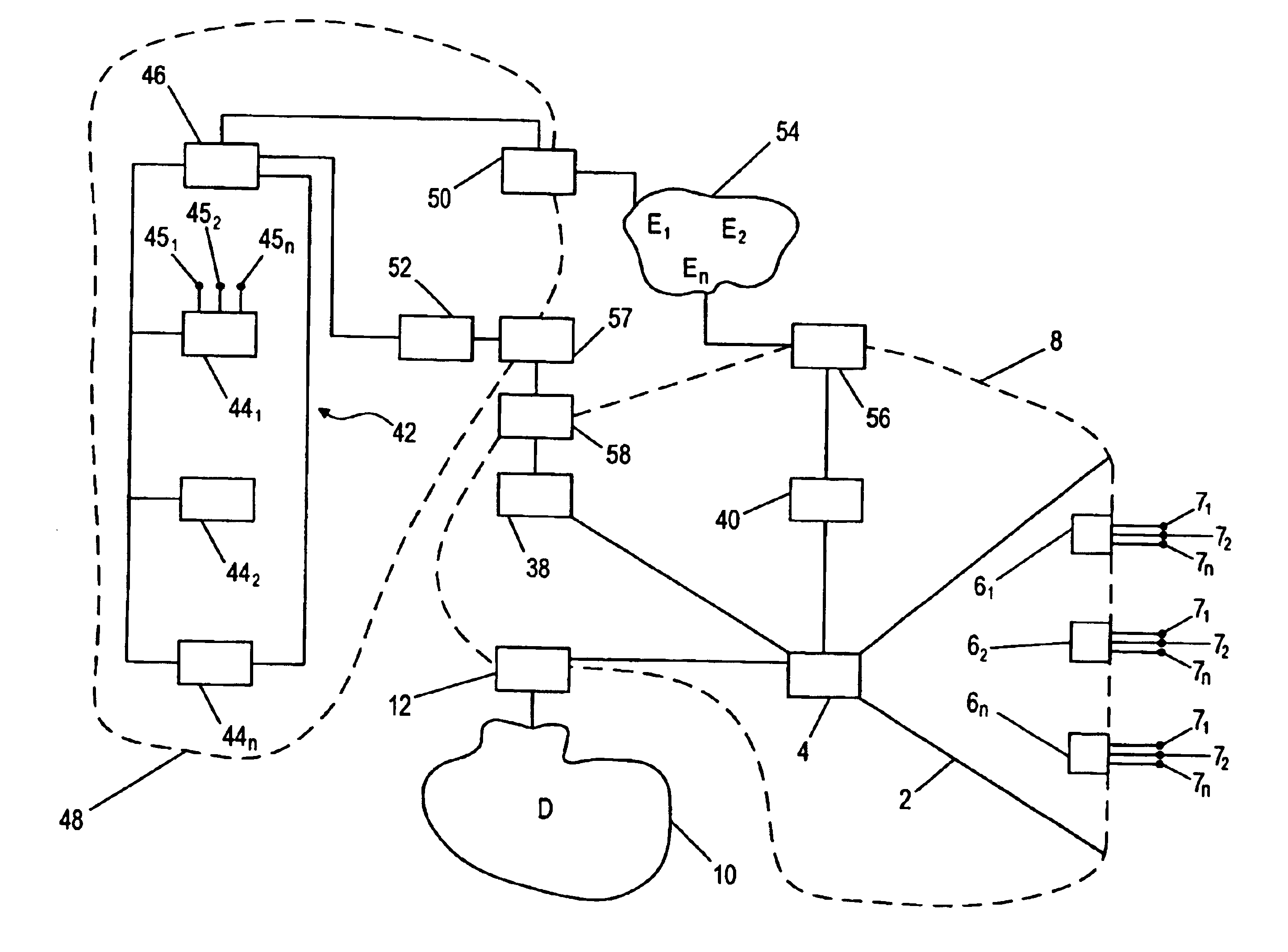
The Internet Protocol (IP) network of FIG. 1 comprises a multiple access (MA) segment (2) served by a switching node (4), such as a radio bass station or a satellite. The structure of the switching node (4) is shown in FIG. 4a and comprises at least one headend (1a) and a switch, more specifically a label switch router comprising a switching function (5) and a switch controller (9). The (MA) segment (2) comprises a broadcast downlink over which the switching node (4) broadcasts simultaneously to all the end systems (6.sub.1, 6.sub.2, . . . 6.sub.n) within the MA segment. The MA segment (2) also comprises an alternative, such as a multi frequency time division multiple access (MFTDMA) uplink over which each end system (6.sub.1, 6.sub.2, . . . 6.sub.n) can communicate with the switching node (4). There may be a high number of end systems within a single MA segment (2). As an alternative to MFTDMA the segment (2) could use time division multiple access (TDMA), frequency division multip...


PUM


Abstract

A communication system having a multiple access segment (2,48), which comprises a plurality of end systems (6,44) and a switching node (4,46) configured such that each end system can transmit packets to the switching node and such that the switching node can transmit packets which are received by all the end systems. The switching node comprises a switch (5,47) for switching packets from the end systems to intermediate destinations within the system, and the MA segment operates in accordance with a protocol which provides a quality of service requested by the end systems for the packets transmitted over the segment. The switching node comprises means for collating primary label routing information for packets to be transmitted from the end systems across the MA segment which primary label is dependent on the intermediate destination of the packet and the QoS requirement of the packet and is independent of the end system from which the packet originates and the switching node switches packets from the end users to the intermediate destinations using only the primary label.

Description

The present invention relates to networks having multiple access (MA) segments and in particular Internet Protocol (IP) networks having MA segments over which multiple end systems communicate over the MA segment with one switching node. The MA segment can, for example, be any satellite, local multi-point distribution system, wireless LAN or cable modem system which uses IP quality of service (QoS) and has a switching node that can broadcast or multicast packets to all end systems and receive packets from all end systems. The end systems can be end user terminals, gateways between the MA segment and other networks or they can be interfacing switches between the MA segment and multiple end user terminals.Such MA segments will generally operate in accordance with a layer It protocol, such as asynchronous transfer mode (ATM), frame relay or ethernet and will provide (QoS) levels required by the packets sent over the segment. Here the term packets is used to denote any parcel of informat...

Claims


Application Information

Patent Timeline
Patent Type & Authority Patents(United States)
IPC IPC(8): H04L12/56
CPCH04L45/00H04L45/16H04L45/50
Inventor ORS, TOLGACABLE, JULIANROSENBERG, CATHERINE
Owner RPX CLEARINGHOUSE
Learn More