
Method and apparatus for measuring NOx gas concentration

a technology of nox gas and concentration, applied in the direction of liquid/fluent solid measurement, electrochemical variables of materials, instruments, etc., can solve the problem of inaccurate measurement of nox concentration, and achieve the effect of reducing temperature dependency and oxygen concentration dependency

Inactive Publication Date: 2004-02-24
NGK SPARK PLUG CO LTD
View PDF42 Cites 34 Cited by
  • Summary
  • Abstract
  • Description
  • Claims
  • Application Information

AI Technical Summary

Benefits of technology

It is therefore an object of the present invention to provide a method for measuring the NOx gas concentration for enabling accurate measurement of the NOx gas concentration in a H.sub.2 O containing atmosphere and a NOx gas concentration sensor for carrying out the method.
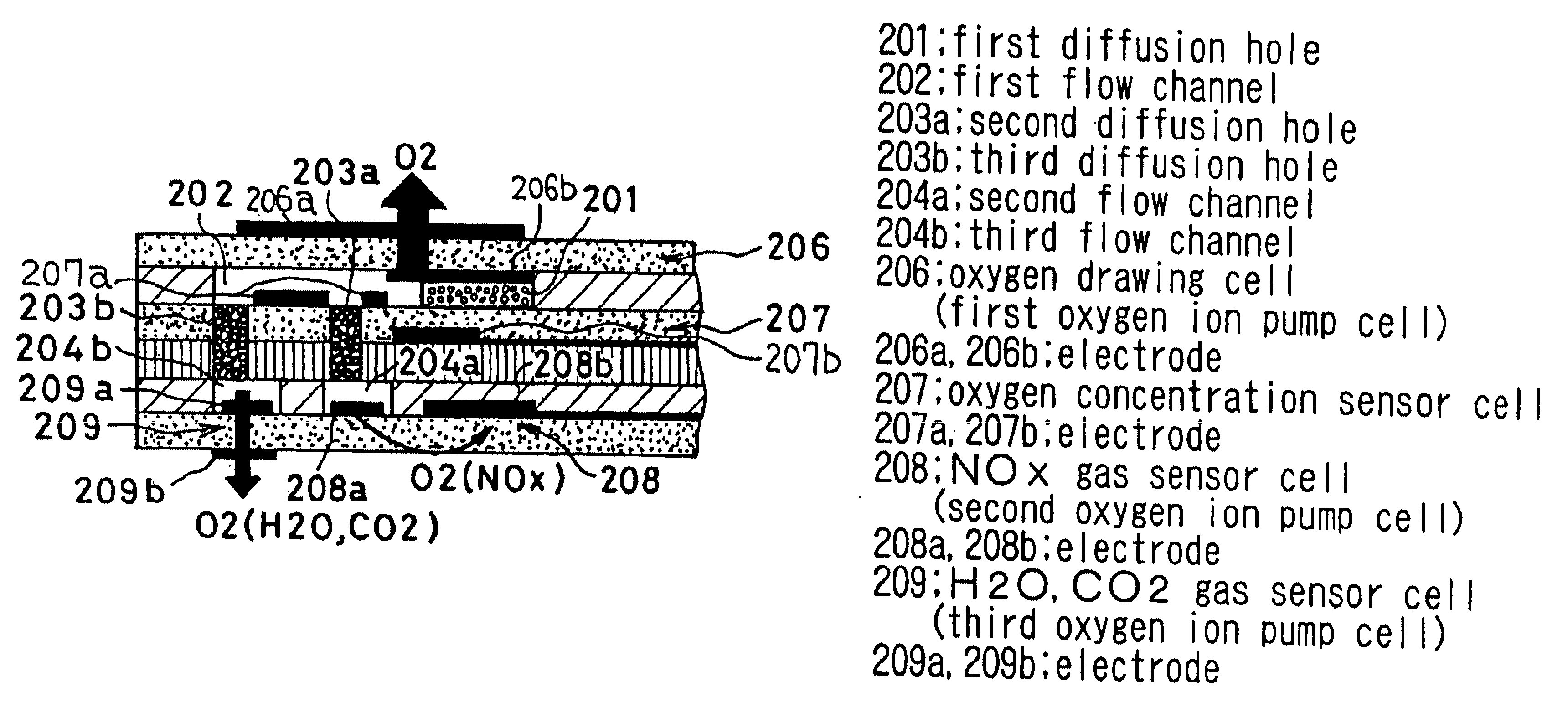
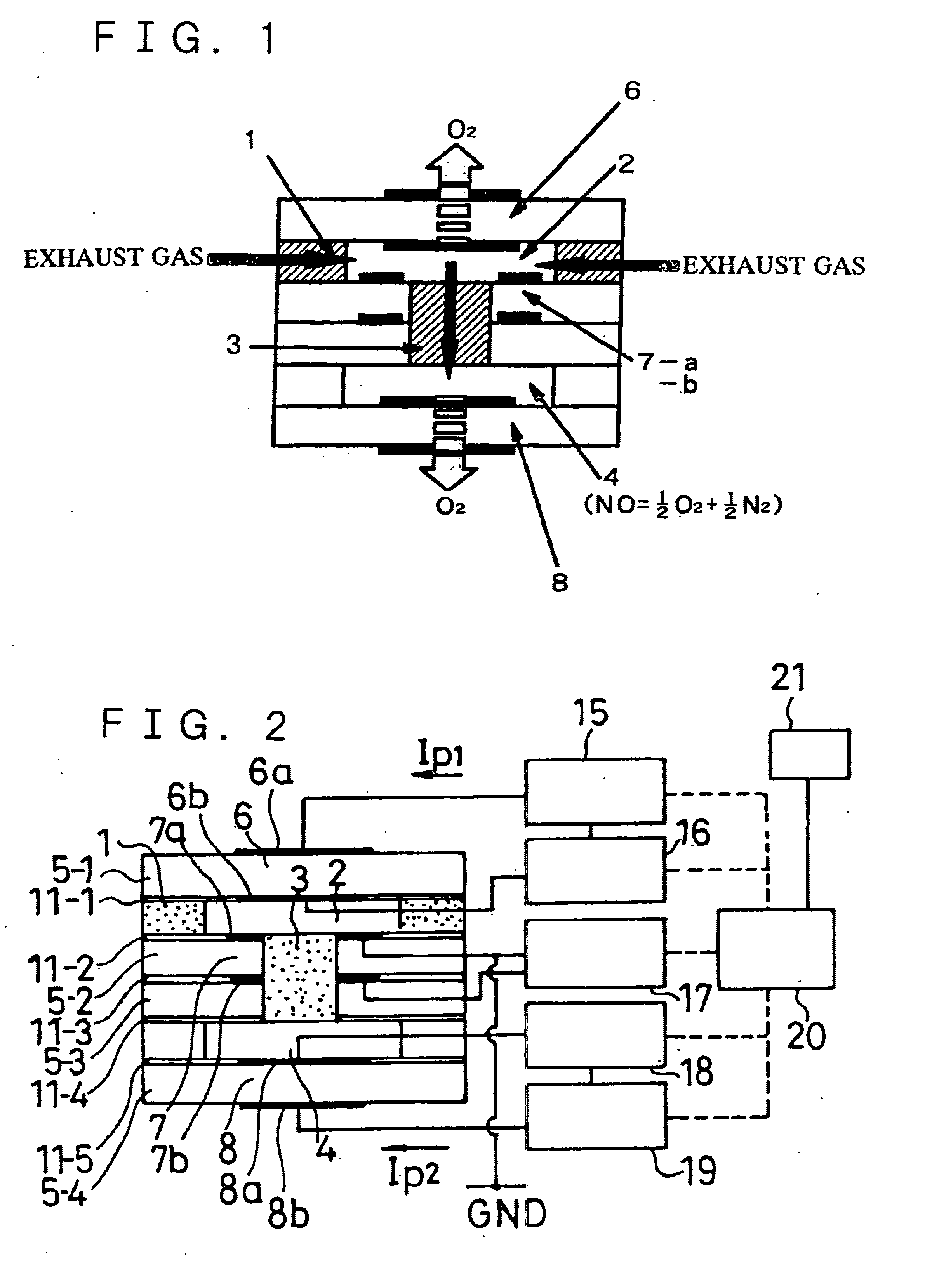
According to aspect 3-1, the voltage impressed across the paired electrodes disposed on inside and outside of the measuring chamber forming a second oxygen ion pump cell is set such as substantially not to dissociate H.sub.2 O present in the measurement chamber. This measurement method is applied to NOx gas concentration detector having a first measurement chamber into which a measurement gas is introduced via a first diffusion resistance, an oxygen partial pressure detection electrode for measuring the oxygen partial pressure in the measurement gas in first measurement chamber, a first oxygen ion pump cell for pumping out the oxygen in the measurement gas in the first measurement chamber to outside of the chamber, based on a potential of the oxygen partial pressure detection electrode, to a sufficient extent of not decomposing the NOx in the measurement gas, a second measurement chamber into which a gas is introduced from the first measurement chamber via a second diffusion resistance and a second oxygen ion pump cell having paired electrodes on an inner and outer sides of the second measurement chamber, the second oxygen ion pump cell being flown through by the current generated by oxygen dissociated on decomposition of NOx in the second measurement chamber on impression of a voltage across the paired electrodes, in which the current flowing through the second oxygen ion pump cell is measured for finding the NOx gas concentration from the current. By setting the voltage impressed across paired electrodes provided on the inner and outer sides of the second oxygen ion pump cell to a pre-set value, it becomes possible to prevent dissociation of H.sub.2 O in the second measurement chamber.
In aspect 3-2 or 3-3 of the present invention, based on the above-mentioned aspect 3-1, since the voltage applied across the second oxygen ion pump cell can be set to 300 to 400 mV or to 400 to 500 mV if the electrode provided on the outer side of the second oxygen ion pump cell is or is not exposed to the atmosphere under measurement, respectively, not only can the effect (1) displayed, but also there occurs (2) decomposition of NOx gas (primarily NO) sufficiently to increase the pump current of the second oxygen ion pump cell produced on NOx gas decomposition, that is to increase the gain, such as to maintain NOx gas concentration measurement (convention or calculation) accuracy.
In aspect 3-4, which is desirable in connection with the above-mentioned aspect 3-1, oxygen in the gas under measurement is pumped out by the first ion pump cell so that the voltage of the oxygen partial pressure sensor electrode will be equal to 150 to 450 mV. This enables the oxygen concentration in the gas diffused into the second measurement chamber to be lowered sufficiently such as not to substantially decompose NOx thus allowing for correct measurement of the NOx gas concentration in an atmosphere which is only slightly affected by the residual oxygen.

Problems solved by technology

According to the finding reached by the present inventors, the above method has a drawback that, if H.sub.2 O is mixed into the NOx gas concentration sensor, the NOx concentration cannot be measured accurately.

Method used


Image

  • Method and apparatus for measuring NOx gas concentration
  • Method and apparatus for measuring NOx gas concentration
  • Method and apparatus for measuring NOx gas concentration

Examples


example c1

Referring to the drawings, a C1 example of the present aspect C is explained.

FIGS. 41A to 41C illustrate a NO.sub.x gas concentration sensor according to an embodiment of the present aspect, where FIG. 41A is a cross-sectional view taken along the long-side direction, FIG. 41B is a plan view showing a first measuring chamber and FIG. 41C is an enlarged cross-sectional view showing essential portions of the first measuring chamber. The sensor of FIG. 41 includes a layer of the first oxygen pumping cell 66 having a solid electrolyte layer and an electrode 66a (positive electrode) and a negative electrode 66b on both sides of the solid electrolyte layer, an oxygen concentration measuring cell 67 having another solid electrolyte layer and an oxygen concentration measuring cell 67 having oxygen partial pressure measuring electrodes formed on both sides of the solid electrolyte layer and a second oxygen pumping cell 68 having a third electrolyte layer and oxygen pumping electrodes on both...


PUM

PropertyMeasurementUnit
voltageaaaaaaaaaa
voltageaaaaaaaaaa
voltageaaaaaaaaaa

Abstract

Method and sensor for measuring accurate measurement of NOx concentration in an exhaust gas containing O2,H2O, CO2 and NOx and a NOx gas concentration sensor. A first oxygen pump cell sufficiently pumps out oxygen in a measurement gas such as not to decompose NOx. A pair of electrodes is provided on an inner side and an outer side of a second measurement chamber into which the gas is introduced from a first measurement chamber via a diffusion resistance. A voltage is impressed across the paired electrodes for decomposing NOx in the second measurement chamber to dissociate oxygen which causes the current to flow in a second oxygen ion pump cell. The NOx gas concentration is measured for this current. The voltage impressed across the paired electrodes of the second oxygen ion pump cell is set so as not to dissociate H2O and CO2 present in the second measurement chamber.

Description

This invention relates to a method for measuring the concentration of the NOx gas and an apparatus or sensor for carrying out the measurement method. More particularly, it relates to a method for measuring the NOx gas concentration used in exhaust gases containing a large quantity of H.sub.2 O, and a NOx gas concentration sensor.Recently, researches into directly measuring the concentration of the NOx gas for controlling the infernal combustion engine or catalysts are proceeding in meeting with intensification of regulations on vehicle exhaust gases.In particular, researches are going on extensively for a NOx gas concentration sensor of the type in which the oxygen is pumped out by a first oxygen ion pump cell using a solid electrolyte (oxygen ion conductor) such as zirconia, so as not to cause decomposition of the NOx gas (2NO.fwdarw.N.sub.2 +O.sub.2) by the first oxygen ion pump cell and in which oxygen is further pumped out from the NOx-gas-containing residual gas by the second o...

Claims


Application Information

Patent Timeline
Patent Type & Authority Patents(United States)
IPC IPC(8): G01N27/407G01N33/00
CPCG01N27/4074
Inventor ANDO, MASASHIISHIDA, NOBORUSUGAYA, SATOSHIOSHIMA, TAKAFUMINADANAMI, NORIHIKOOOTUKA, TAKAKISATO, YOSHIKUNIOKUMURA, TATSUO
Owner NGK SPARK PLUG CO LTD
Learn More