
Actuator device utilizing a conductive polymer gel

a technology actuator device, which is applied in the field of conductive polymer gel, can solve the problems of not being able to scale down and replicate macroscopic designs, not being able to report the direct measurement of the mechanical response of these materials to electrochemical stimulation, and only being able to design

Inactive Publication Date: 2004-02-03
SANDIA NAT LAB
View PDF5 Cites 130 Cited by
  • Summary
  • Abstract
  • Description
  • Claims
  • Application Information

AI Technical Summary

Benefits of technology

"The present invention is about a new type of conductive polymer gel that can be used as a micro-actuator to open and close valves and pumps in small analytical instruments. The gel is responsive to low electrical potentials and can change its size and extension when an electric current is applied. The actuator is made by creating a polymer gel that can change its shape when an electric current is applied. The gel can be used in miniaturized systems and has the potential to be a fast and efficient actuator. The invention also includes a method for measuring the force generated by the gel and a device made using the gel. The technical effects of the invention are the creation of a new actuator that is responsive to low electrical potentials and the development of a method for measuring the force generated by the actuator."

Problems solved by technology

However, it is generally recognized that these designs will only be possible with the development of fast and efficient micro-actuators that can be operated as pumps and valves.
As is often the case, however, such macroscopic designs are not easily scaled down and replicated as microdevices and still providing acceptable function.
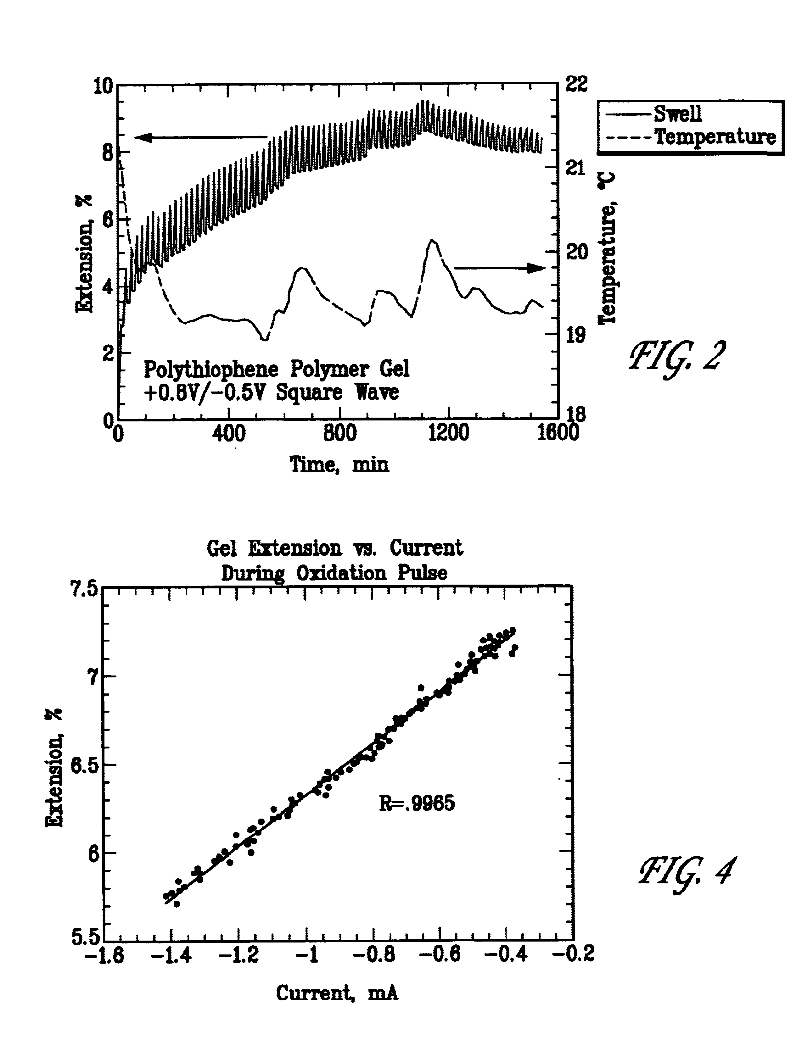
While a large body of prior art exists describing electrochemically driven swelling / de-swelling of conductive polymers none of the work in the literature has reported the direct measurement of the mechanical response of these materials to electrochemical stimulation.
Presumably, therefore, none have recognized the potential use of these materials as control members in micro-actuators.
Rather, it falls monotonically with increasing pulse time.

Method used


Image

  • Actuator device utilizing a conductive polymer gel
  • Actuator device utilizing a conductive polymer gel
  • Actuator device utilizing a conductive polymer gel

Examples


Embodiment Construction

and Best Mode

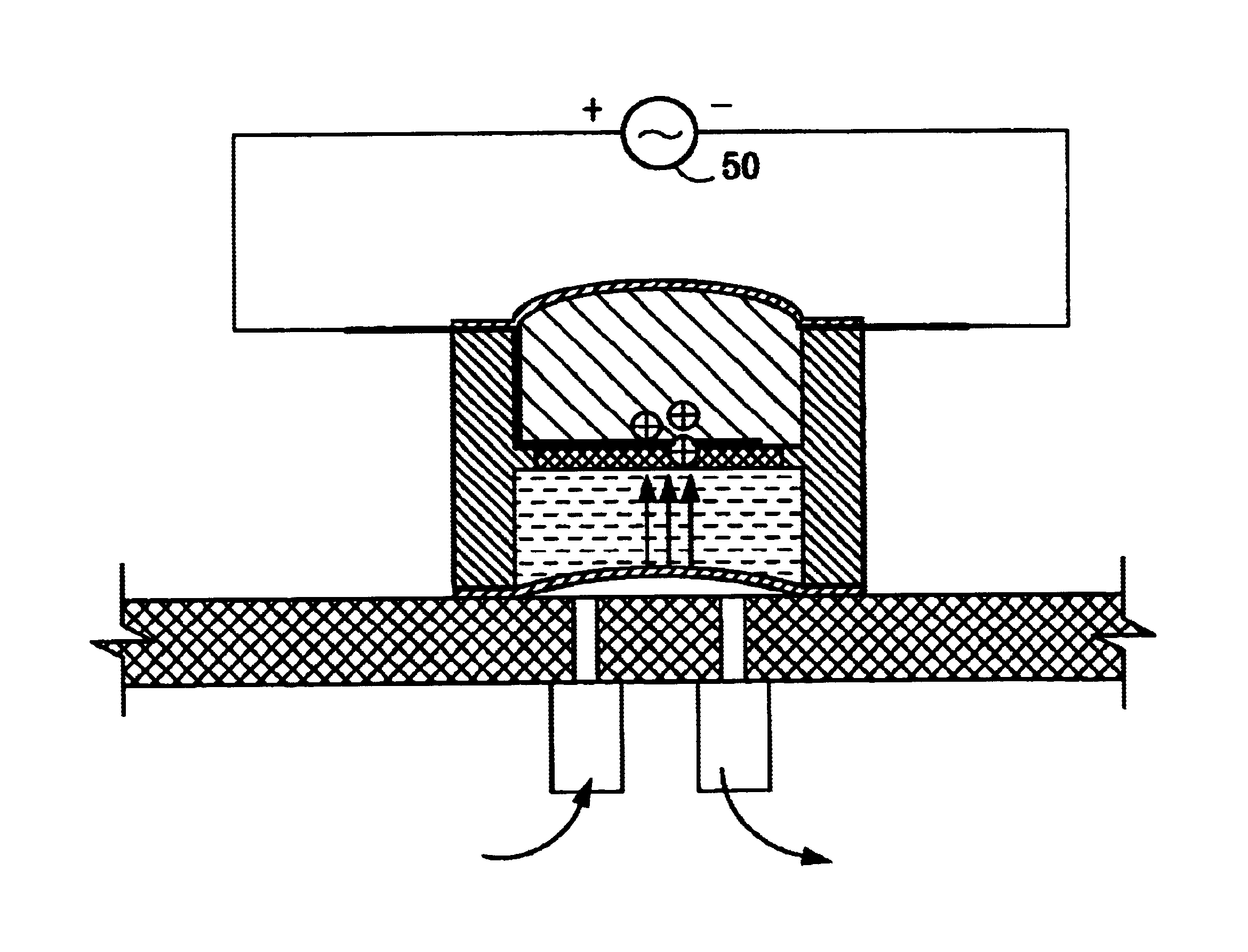
The gel of the present invention finds utility as a seal or diaphragm to regulate or control flow through miniature actuator assemblies. In one embodiment, illustrated in FIGS. 6-10, a small cylindrical plug 12 of the gel is formed in a mold or cut from a sheet of the polymer. Electrodes 15, formed by attaching a disk of a conductive porous mesh 14 to an electrode wire 11, as shown in FIG. 6B, are attached at top and bottom surfaces of plug 12, as shown in FIG. 6A, to form plug assembly 10. Alternatively, disk 14 may be a thin metal layer deposited directly onto a portion of the surface of gel plug 12, either by vapor, chemical or particle deposition, or low temperature sputtering.

Once formed, plug assembly 10 is immersed in an electrolyte solution, comprising charge balancing ions and an associated coordinated solvent species molecule. Although other solvent / salt systems are possible, the particular electrolyte system used in the present invention comprised a quaternar...


PUM

PropertyMeasurementUnit
electrical potentialaaaaaaaaaa
temperatureaaaaaaaaaa
densityaaaaaaaaaa

Abstract

A valve actuator based on a conductive polymer gel is disclosed. A nonconductive housing is provided having two separate chambers separated by a porous frit. The conductive polymer is held in one chamber and an electrolyte solution, used as a source of charged ions, is held in the second chamber. The ends of the housing a sealed with a flexible elastomer. The polymer gel is further provide with electrodes with which to apply an electrical potential across the gel in order to initiate an oxidation reaction which in turn drives anions across the porous frit and into the polymer gel, swelling the volume of the gel and simultaneously contracting the volume of the electrolyte solution. Because the two end chambers are sealed the flexible elastomer expands or contracts with the chamber volume change. By manipulating the potential across the gel the motion of the elastomer can be controlled to act as a "gate" to open or close a fluid channel and thereby control flow through that channel.

Description

1. Field of the InventionThe present invention relates to a conductive polymer gel and its application for driving a miniature actuator. In particular the present invention is drawn to a polythiophene-based conductive polymer gel used to open and close an actuator valve.2. Background and Related ArtCurrent trends in the designs of analytical instrumentation, especially where fluids are used to carry analytes to various instrument stations for processing (such as separation, mixing, species detection, and the like), are increasingly tending toward integrated and miniaturized systems. However, it is generally recognized that these designs will only be possible with the development of fast and efficient micro-actuators that can be operated as pumps and valves. As analytical equipment is scaled down the mechanical structures comprising these devices must also decrease in size. As is often the case, however, such macroscopic designs are not easily scaled down and replicated as microdevic...

Claims


Application Information

Patent Timeline
Patent Type & Authority Patents(United States)
IPC IPC(8): F04B43/02F04B43/04F15C5/00F04B19/24F04B17/00F04B19/00B01L3/00G01N35/00F16K99/00
CPCF04B17/00F04B19/24F04B43/043F15C5/00F16K99/0001F16K99/0007F16K99/0015F16K99/0025F16K99/0042F16K99/0059B01L3/5027F16K2099/0076F16K2099/0078F16K2099/0094G01N2035/00247
Inventor CHINN, DOUGLAS A.IRVIN, DAVID J.
Owner SANDIA NAT LAB
Learn More