Electrosurgical device having a dielectric seal

a dielectric seal and electrosurgical technology, applied in the direction of coupling device engagement/disengagement, surgical instruments for heating, medicine/surgical connectors, etc., can solve the problems of difficult sterilization and reuse of the device, and the conductive fluid can provide an undesirable conductive path from the electrod

Inactive Publication Date: 2007-12-25
COVIDIEN AG
View PDF126 Cites 269 Cited by
  • Summary
  • Abstract
  • Description
  • Claims
  • Application Information

AI Technical Summary

Problems solved by technology

These fluids and bio-materials may deposit on the control mechanisms and wires within the housing thereby making it difficult to sterilize and reuse the device.
Additionally, conductive fluids can provide an undesirable conductive path from the electrode to the surgeon and other objects in the surgical site, if fluid enters the nose or actuator areas.

Method used


Image

  • Electrosurgical device having a dielectric seal
  • Electrosurgical device having a dielectric seal
  • Electrosurgical device having a dielectric seal

Examples


first embodiment

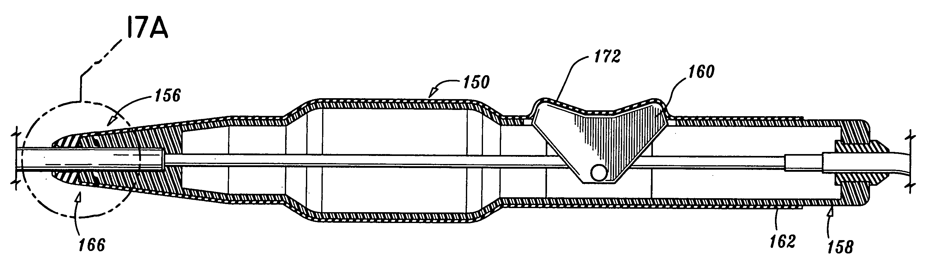
[0062]With reference now to FIGS. 14-18, an elastomeric seal of a first embodiment will be described which is designated generally by reference numeral 150. Seal 150 of FIG. 14 is designed to fit upon a standard electrosurgical device of the type shown by FIG. 15 and designated generally by reference numeral 152. Similarly to electrosurgical device 10, electrosurgical device 152 is suitable for use in surgical procedures such as cauterizing, cutting and similar procedures. Electrosurgical device 152 introduces RF cauterizing current, cutting current, or a blend thereof to an electrode 154 protruding from a nose area 156 of a longitudinal housing 158 by means of a finger-operated switch actuating member 160 disposed on housing 158.

[0063]Elastomeric seal 150 includes an elongated body portion 162 having a first opening 164 at a distal end 166 to accommodate varying diameters of electrodes or blades connected to electrosurgical device 152. A second opening 168 is defined at a proximal ...

second embodiment

[0067]With reference to FIGS. 19 and 20 there is shown an elastomeric seal of a second embodiment designated by reference numeral 200 and attached to nose area 156 of electrosurgical device 152. Seal 200 is chemically adhered to the nose area 156 which allows for seal 200 to be reusable. It is also contemplated that seal 200 can be mechanically attached to nose area 156 by rivets or other type of mechanical structure for allowing seal 200 to be disposable. It is further contemplated that seal 200 can be friction fit to nose area 156 of the electrosurgical device as well. Elastomeric seal 200 includes a soft lip 202 and an opening 204, as in the embodiment of FIGS. 14-18, to permit electrodes and blades of varying diameters to be inserted and sealed as shown by FIG. 20.

[0068]It is contemplated that seal 200 can be custom-molded for a particular electrosurgical device. Seal 200 is preferably manufactured from shore A durometer silicone or a thermoplastic elastomer. Seal 200 can be ste...


PUM

PropertyMeasurementUnit
lengthaaaaaaaaaa
lengthaaaaaaaaaa
dielectricaaaaaaaaaa

Abstract

A method of manufacturing a seal in an electrosurgical device includes placing components of the electrosurgical device within an elongated housing section, the housing section including an actuator opening, introducing the housing section within a mold filled with a liquid thermoplastic elastomer and allowing the elastomer to flow within the housing, forming an elastomeric inwardly-extending lip portion circumferentially surrounding an opening at a distal end of the electrosurgical device for introducing an electrode therein, and allowing the molded elastomer to cure and become integral with the housing to seal the components within the molded elastomer contained within the housing section. The method may also include the step of forming an elastomeric actuator seal around the actuator opening.

Description

[0001]This application is a divisional of U.S. patent application Ser. No. 09 / 396,897 filed on Sep. 15, 1999, issued on Jun. 11, 2002 as U.S. Pat. No. 6,402,748, which claims priority to U.S. Provisional Patent Application Nos. 60 / 101,489 and 60 / 105,367 filed on Sep. 23, 1998 and Oct. 23, 1998, respectively, the disclosures of which are hereby incorporated by reference herein.BACKGROUND[0002]1. Technical Field[0003]This disclosure relates generally to an electrosurgical device of the type having an actuator for alternating between a cauterizing and a cutting mode. More particularly, the present disclosure relates to an electrosurgical device having an elastomeric seal for providing bio-contamination and dielectric protection by preventing fluids from entering the nose and actuator areas of the electrosurgical device.[0004]2. Background of the Related Art[0005]Electrosurgical devices suitable for use in surgical procedures such as cauterizing, cutting and similar procedures are well ...

Claims


Application Information

Patent Timeline
Patent Type & Authority Patents(United States)
IPC IPC(8): A61B18/18B29C39/24A61B17/00A61B18/00A61B18/14G06M1/04G06M1/08H01H1/18H01H9/04H01H9/06H01R13/66H01R43/26
CPCG06M1/04G06M1/083H01H1/18H01H9/04H01H9/06H01R13/66A61B18/1402A61B18/14H01R2201/12A61B2017/00026A61B2017/00035A61B2017/00057A61B2017/0046A61B2017/00526A61B2018/00178A61B2018/00988H01H2300/014H01R43/26
Inventor SCHOENMAN, ARTHURSARTOR, JOE D.KELM, VERNITA
Owner COVIDIEN AG
Why Eureka
Try Eureka