
Method of optimizing the design, stimulation and evaluation of matrix treatment in a reservoir

a matrix treatment and reservoir technology, applied in the direction of liquid handling, survey, borehole/well accessories, etc., can solve the problems of matrix treatment being a main contributor to reservoir damage, increasing the complexity of treatment fluid recipes, and forming precipitates

Inactive Publication Date: 2003-12-30
SCHLUMBERGER TECH CORP
View PDF3 Cites 90 Cited by
  • Summary
  • Abstract
  • Description
  • Claims
  • Application Information

AI Technical Summary

Benefits of technology

In a second embodiment of the invention, the method further includes modeling a reservoir core having a length, a diameter and a permeability so that the invention makes it possible to simulate core tests. The invention also provides a way to simulate sequential treatments where successions of treatment fluids are injected at specific rates.
In a third embodiment of the invention, the method further includes scaling up the treatment to a reservoir using a mathematical model to predict damages resulting from the treatment. In a most preferred embodiment, the invention includes selecting a treatment, carrying out the treatment on a well while real time damage are computed based on bottomhole pressure and injection rate and simultaneously, performing a simulation scaled up to the reservoir to compare the predicted damages and the computed damages and adjusting the treatment if required.
In this embodiment, three flow geometries are implemented in the simulator. These are batch, core and reservoir flow geometries. The batch flow geometry approximates reactions occurring in a flask or a beaker, the core flow geometry approximates linear flow in cores such as that in laboratory core flooding experiments, and the reservoir flow geometry approximates flow in a single layer, radially symmetric reservoir. The batch and core flow geometries provide a means for validating the mathematical model, so that the predictions for the reservoir can be made we more confidence. For example, the geochemical simulator can be validated with measured effluent ion concentrations and the permeability evolution from laboratory core flow experiments, prior to making predictions for the reservoir.
The model generated by the method of the subject invention can facilitate optimization of matrix treatments by providing a rapid quantitative evaluation of various treatment strategies for a formation. Stimulation with non-traditional fluid recipes containing mixtures of inorganic and organic acids, and chelating agents can be readily computed. The computed values can then be used in an economic model to justify the additional costs associated with the use of the non-traditional fluids. Apart from optimizing matrix treatments, the method of the subject invention can also be used as a development tool for new fluid systems, as a tool for prediction and removal of inorganic scale and for fluid compatibility testing such as that required in waterflooding projects.
The method of the subject invention combines a geochemical simulator to an extensive database of thermodynamic properties of aqueous chemical species and minerals. The subject invention overcomes many limitations of previous simulators. Chemical equilibrium calculations can be performed between any number of minerals and aqueous solutions, whereas previous simulators were limited to only one or two precipitated minerals. Additionally, any number of kinetically controlled reactions can be simulated with user-defined kinetics.

Problems solved by technology

Treatment fluid recipes have become increasingly complex.
However, matrix treatments are also often a main contributor to reservoir damages.
Indeed, the side reactions that occur in almost all mud acid treatments, lead to the formation of precipitates.
Precipitates plug pore spaces and reduce permeability and can therefore adversely affect acid treatments if precipitates deposit near the wellbore.
Moreover, sandstone mineralogy is quite complex and acid / mineral compatibility as well as acid / crude oil compatibility is often an issue.
At present, there is a lack of tools that can predict accurately the reactivity of acids with clays, and consequently, there are treatments currently in practice that use empirical rules--or at the opposite extreme, rely on extensive costly and time-consuming laboratory testing.
Disadvantages of lumped mineral models are that they do not allow for equilibrium reactions to be modeled and need to be carefully calibrated to the treatment condition and formation of interest.
Therefore, these models are not applicable to fluids systems containing weak acids (e.g. most organic acids) and chelating agents and are not reliable outside the calibrated region.
Unfortunately, the assumption that the reactions are much faster than the contact time is not valid for the injection rates used in most acid treatments and thus the equilibrium approach is useful only as an indicator for precipitation.
An equilibrium model alone with no time dependence cannot answer this question.
First, accurate computation of the activity coefficients for high acidic and high ionic strength solutions is difficult.
Second, due to inefficient numerical algorithms numerical convergence was a frequent problem.
Third, only a limited thermodynamic data was available.
Hence, simulations for hot reservoirs and with nontraditional fluid systems were not possible.
So yet, despite the important risk of damaging a reservoir, no satisfactory method for modeling matrix treatments over a much broader range of these variables, to make the model more reliable for extrapolating laboratory data to field conditions.
This failure of the existing models is all the more critical that treatment fluid recipes have become increasingly complex.
Typical matrix stimulation fluids are extremely non-ideal.

Method used


Image

  • Method of optimizing the design, stimulation and evaluation of matrix treatment in a reservoir
  • Method of optimizing the design, stimulation and evaluation of matrix treatment in a reservoir
  • Method of optimizing the design, stimulation and evaluation of matrix treatment in a reservoir

Examples


Embodiment Construction

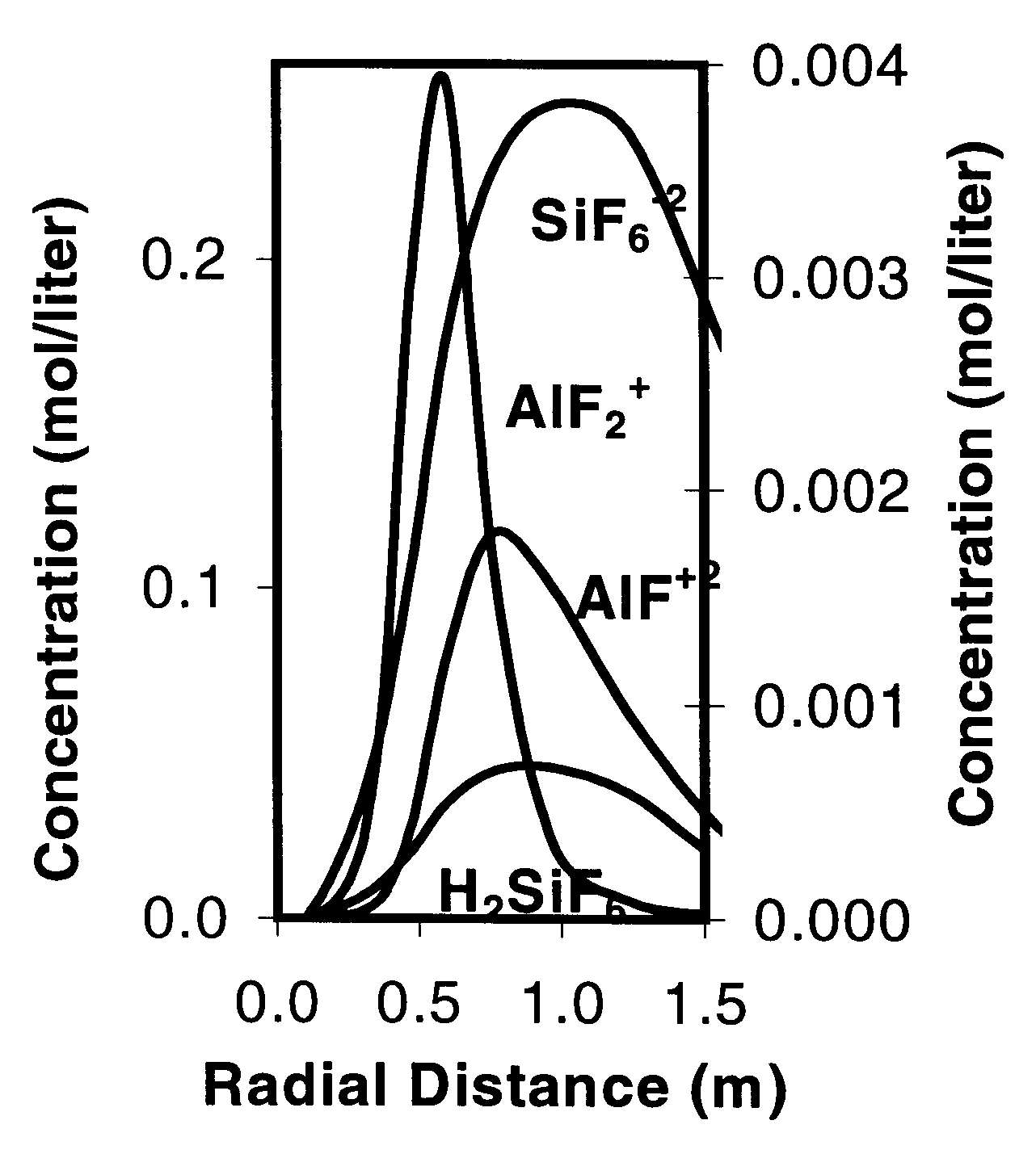
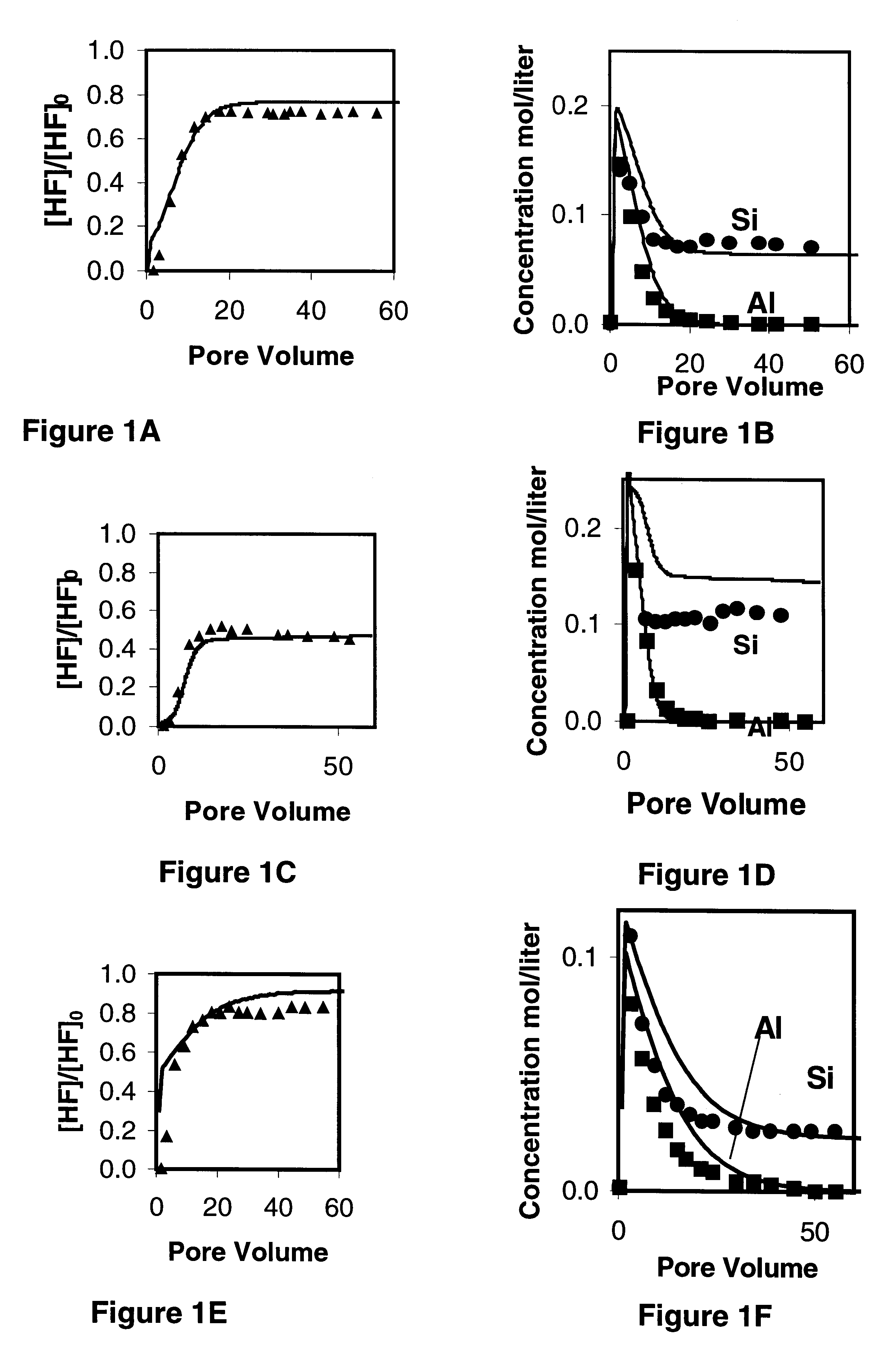
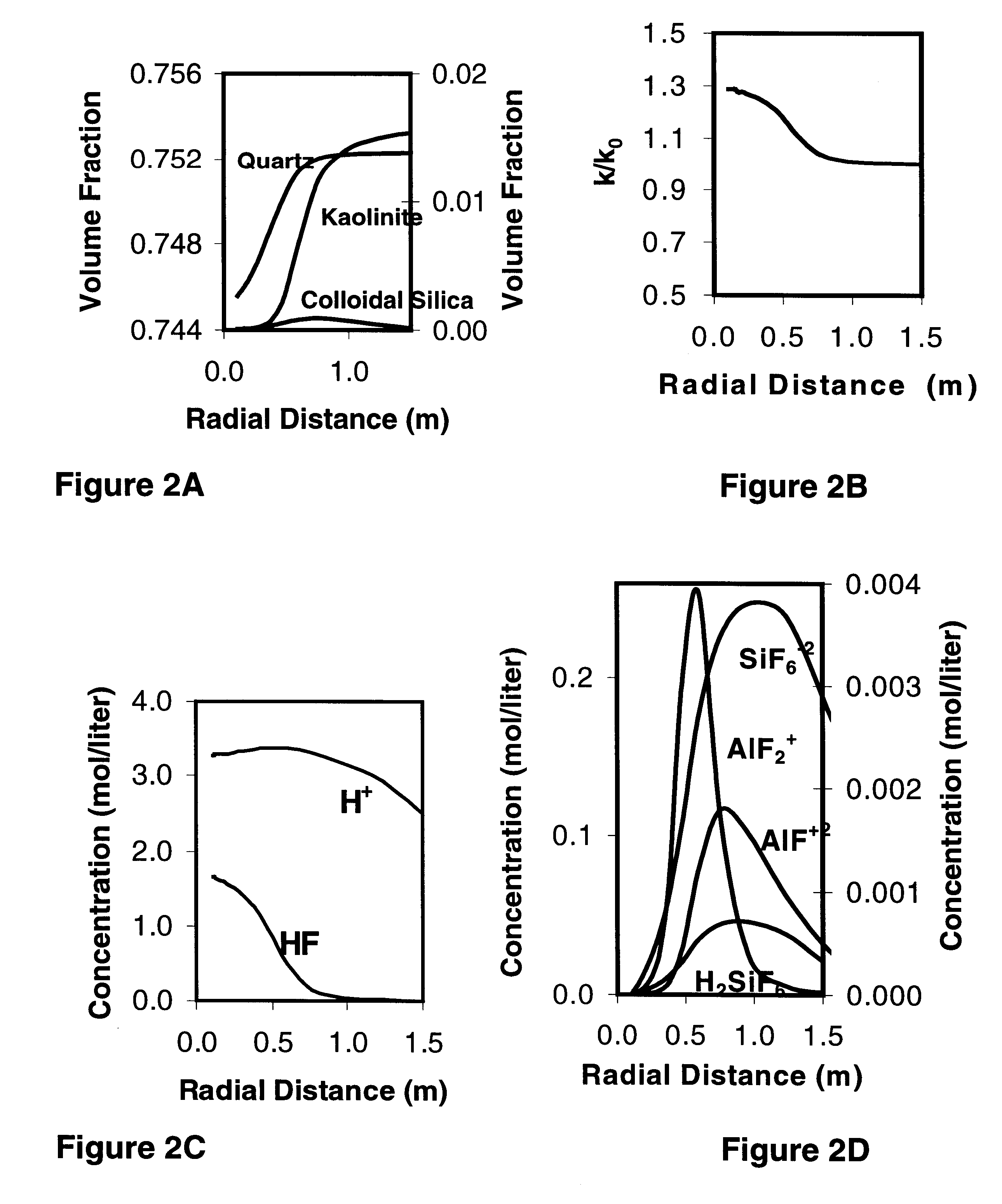
The main features of the invention are illustrated in this section by means of a simple application example. The example is based on core test data reported by Hsi et al (IN Hsi, C. D., S. L. Bryant, and R. D. Neira, SPE 25212 Experimental Validation of Sandstone Acidization Models, in SPE International Symposium on Oilfield Chemistry. 1993. New Orleans) for the Endicott Kediktuk sandstone formation in Alaska. The core tests were conducted on damaged cores at 80.degree. C. with 12 / 3 Mud acid. The length and diameter of the core plugs were 7.6 and 2.54 cm, respectively. An inductively coupled plasma (ICP) spectrophotometer was used to measure effluent Al and Si concentrations. The HF concentration in the effluent was measured gravimetrically using the weight-loss method with pre-weighted glass slides. The mineralogy of the Kekiktut formation is 98% Quartz and 2% kaolinite.

FIG. 1 shows a comparison of the measured effluent concentration of HF, Al, and Si with those predicted by the mo...


PUM

PropertyMeasurementUnit
Temperaturesaaaaaaaaaa
diameteraaaaaaaaaa
diameteraaaaaaaaaa

Abstract

A method for designing acid treatments provides for the selection of optimal treatment for well stimulation wherein reservoir characteristics are obtained to further select the reaction kinetic data on the minerals of interests, the treatment to the reservoir is scaled up using a mathematical model and real time damage are computed based on bottomhole pressure and injection rate and compared to that predicted by the mathematical model to adjust the treatment. The model generated facilitates optimization of matrix treatments by providing a rapid quantitative evaluation of various treatment strategies for a formation. Stimulation with non-traditional fluid recipes containing mixtures of inorganic and organic acids, and chelating agents can be readily computed. The computed values can then be used in an economic model to justify the additional costs associated with the use of the non-traditional fluids. Apart from optimizing matrix treatments, the method can be used as a development tool for new fluid systems, as a tool for prediction and removal of inorganic scale and for fluid compatibility testing such as that required in water flooding projects.

Description

1. Field of the InventionThe present invention is generally related to hydrocarbon well stimulation, and is more particularly directed to a method for designing matrix treatment, or generally any treatment with a fluid that will react with the reservoir minerals or with chemicals resulting for instance from a previous treatment. The invention is particularly useful for designing acid treatment such as for instance mud acid treatments in sandstone reservoirs.2. Discussion of the Prior ArtMatrix acidizing is among the oldest well stimulation techniques. It is applied to sandstone formations to remove near-wellbore damage, which may have been caused by drilling, completion, production, or workover operations. Matrix acidizing is accomplished by injecting a mixture of aids (typically hydrofluoric and hydrochloric acids) to dissolve materials that impair well production, as a rule designated as near-wellbore damages.Matrix treatments ma sandstone reservoirs have evolved considerably sinc...

Claims


Application Information

Patent Timeline
Patent Type & Authority Patents(United States)
IPC IPC(8): E21B43/25E21B41/00A61L2/20B65B55/02B65B55/10B67C7/00
CPCA61L2/20B65B55/025E21B43/25B67C7/0073B65B55/10
Inventor ZIAUDDIN, MURTAZAROBERT, JOEL
Owner SCHLUMBERGER TECH CORP
Learn More