In one aspect, the
capacitive sensing system includes a power source to supply electrical charge; a
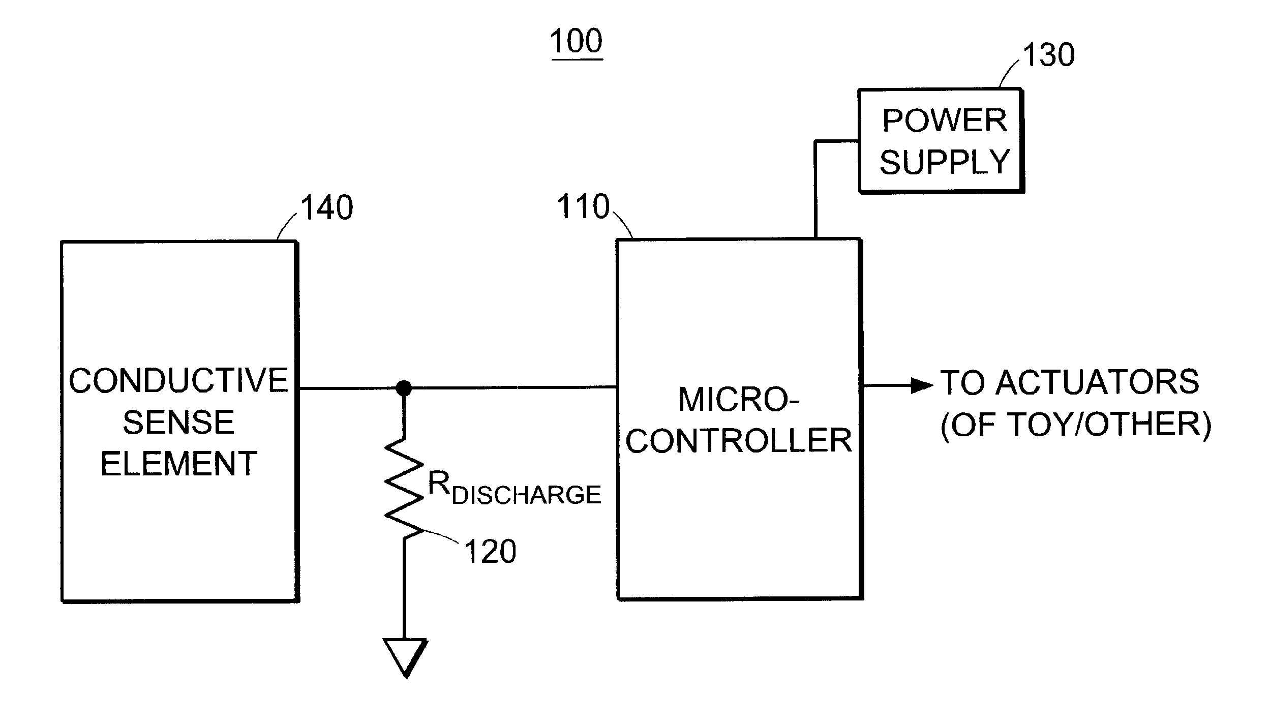
microcontroller, in communication with the power source and having at least one digital logic input / output (I / O) pin; a conductive sense element (which may be a plate, surface, wire, thread or
conductive ink pattern) coupled to the port, and a resistance element coupled to the sense element. A
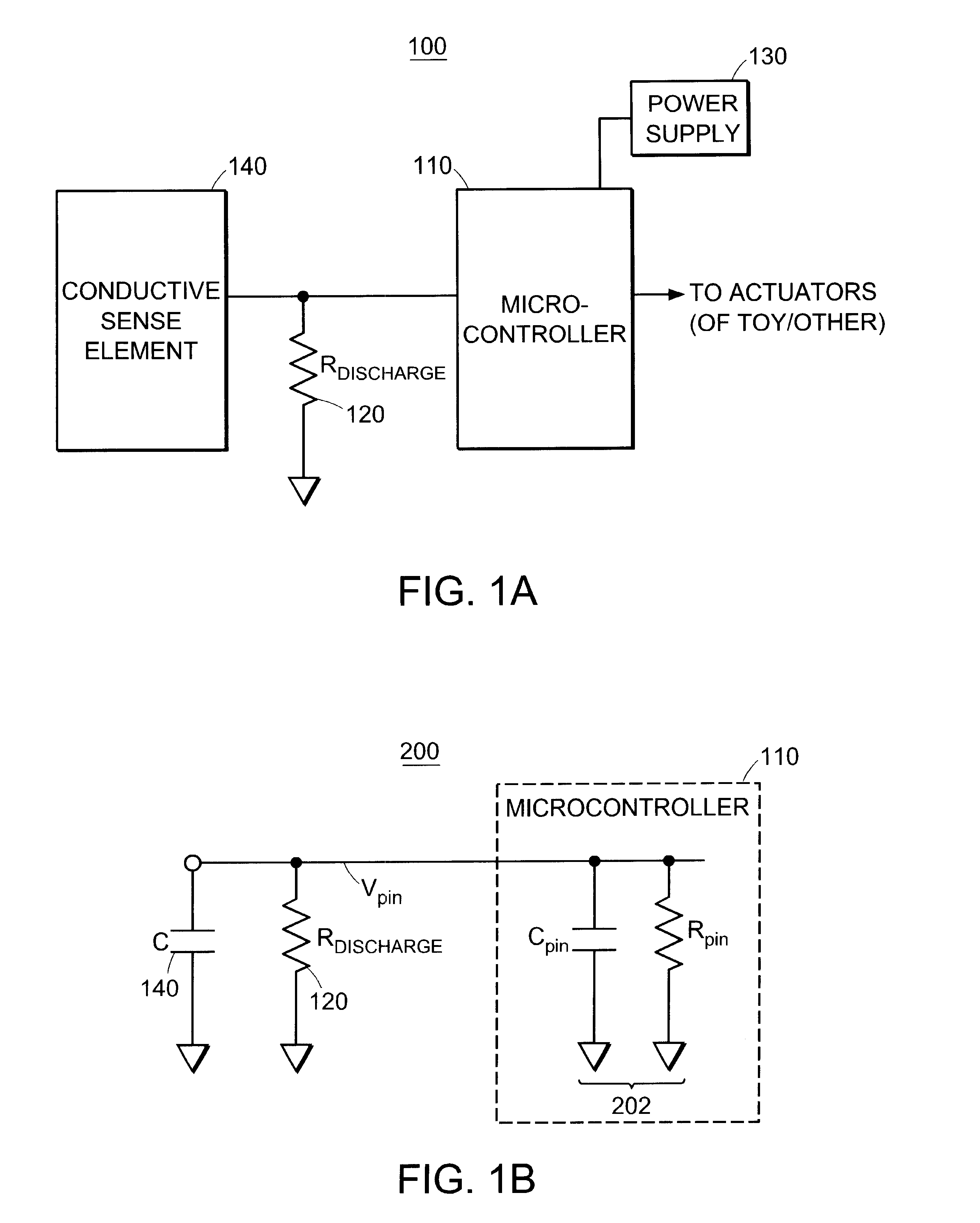
variable capacitor configuration is formed by the sense plate and an object (such as a human hand) in proximity to the sense plate, and the
capacitance thereof is representative of the proximity of the object to the sense element. After the conductive sense element is charged by a
voltage placed on the I / O pin, the time (or other parameter) necessary to
discharge the sense element through the resistance element can be measured to determine the
capacitance, and thus the proximity of an object to the sense element. By digitally
processing the signals on the I / O pin, the
system can provide resolution enhancement, automatic and continuous calibration,
noise reduction and
pattern recognition. In particular, the
system can be made sensitive to very small changes of
capacitance, despite large sensor offsets; relatively insensitive to random sensor
noise caused, for example, by nearby electrical circuitry; self calibrating at the factory to compensate for variations in
chip specifications and other manufacturing tolerances; and auto-calibrating to compensate for drift over time.
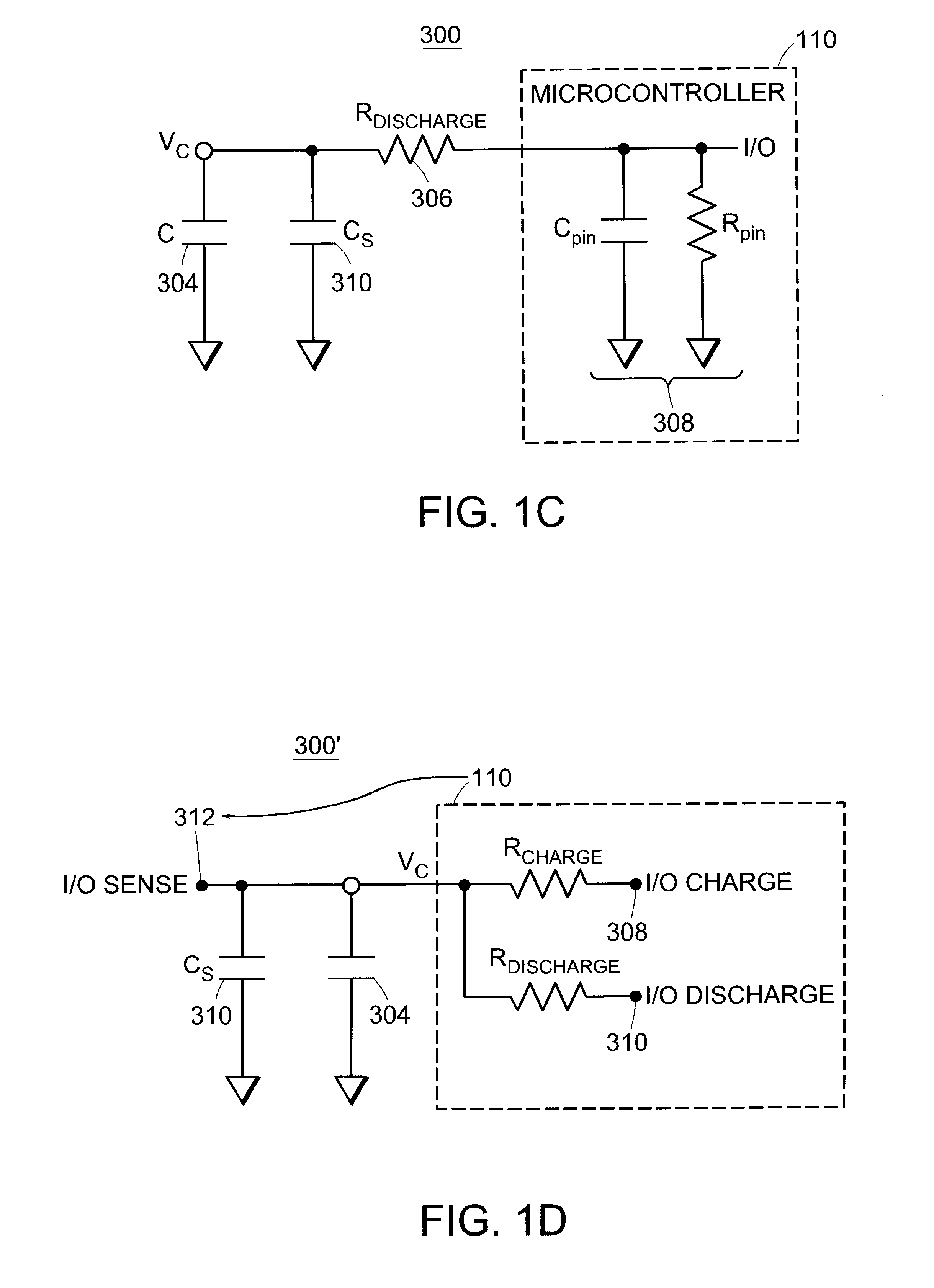
In one aspect of the invention, capacitance is measured by measuring the time required to
discharge the capacitance through a resistance using the above-described configuration of microcontroller I / O pin, sense element and
resistor. In accordance with this aspect, a method includes: setting the I / O pin to OUTPUT mode with its state HIGH, thus charging the
capacitor to the supply
voltage of the microcontroller; then setting the I / O pin to INPUT mode (referred to hereinafter as changing the direction of the I / O pin or turning around the I / O pin); and then measuring the time required for the
voltage measured at the pin (V.pin) to fall below the
threshold voltage of the microcontroller. The measured
discharge time is approximately proportional to the resistance of the
resistor (R.discharge) times total capacitance (C). Since the microcontroller uses a stable
clock,
digital signal processing techniques are employed to make high-resolution measurements of time. In this way, small changes in capacitance (C) can be reliably measured.
A pet sensor detects a petting contact and distinguishes it from other types of touch (and from noise), using techniques similar to the
rhythm sensor, but also including a bandpass filter to preprocess the
signal before the detection of rising and falling edges. In this preprocessing, the raw capacitive sensor values are passed first to a low-pass filter. The output of the low-pass filter is then filtered again through a high-pass filter. In applications that can afford the use of a small amount of extra memory for the filtering operations, this results in significantly better performance in distinguishing a true petting motion from other kinds of touch and spurious noise.
The invention provides numerous technical advantages. For example, the sensor utilizes existing I / O and stable
clock source of standard, low-cost microcontrollers already present in many "smart" objects; and since the system uses only limited microcontroller resources (a sense element requires only a single I / O pin), one microcontroller can support many sensors (eight sensors can be operated from a typical 8-bit digital logic port). The hardware configuration of the invention requires only one
external resistor per sensor, further reducing cost; and no
variable frequency oscillator,
frequency divider, or specific sense-plate geometries or materials are required. Integrated capacitive sensing and
signal processing capabilities are thus provided with far fewer components and at lower cost than previously possible. The sensors are automatically and continuously calibrated, and integrated noise rejection reduces the incidence of false positives.
In practical applications, such as toys, the invention can reliably detect touch through several
layers of fabric or stuffing or plastic; does not require metallic or other potentially dangerous components exposed on the outside; can be natural looking and feeling, thus enabling a more natural, non-mechanical interaction than that provided by conventional mechanical switches. Still further, the invention can detect not only touch, but also patterns of touch, such as tickle, pet, bounce, squeeze, burp, slap, or other. In a toy, this enables detection not only of whether a child is playing with the toy, but how the child is playing with the toy. The virtual sensor aspects of the system (e.g., a
proximity sensor; a tickle sensor; a pet sensor) can compile and synthesize a wide range of information from one or more simple physical sensors (such as a pattern of
conductive ink); and enable recognition and "learning" of
signal patterns or signatures. This enables a powerful interactivity capability, since the toy or other object "knows" how it is being manipulated (squeeze, tickle, pet, slap, or other) and can even "learn" the interactivity patterns of its user(s).


