
Apparatus and method for preparing winding mandrels and cores for rewinding machines

a winding machine and winding core technology, applied in the directions of transportation and packaging, thin material processing, filament handling, etc., can solve the problems of wound material being subject to shrinkage, time-consuming, labor-intensive, and labor-intensive, and the process is time-consuming and labor-intensiv

Inactive Publication Date: 2003-12-02
A CELLI NONWOVENS
View PDF10 Cites 38 Cited by
  • Summary
  • Abstract
  • Description
  • Claims
  • Application Information

AI Technical Summary

Benefits of technology

The object of the present invention is to provide an apparatus or device which makes it possible to overcome the disadvantages, the limitations and the possibilities of error of the conventional systems.
The cutting tool is advantageously carried by an oscillating arm which controls its movements toward and away from the mandrel, although the possibility of using mechanisms of another type for moving the cutting tools toward and away from the mandrel is not excluded. The use of an oscillating arm is particularly advantageous in terms of mechanical simplicity. Additionally, in this way it is easy to provide a system of stops which define the operating position, in other words a plurality of operating positions of the tools, which can be selected alternatively according to the diameter of the mandrel and therefore of the tube to be cut.

Problems solved by technology

This procedure is time-consuming, tiring, and labor-intensive.
Moreover, since the individual tubular cores fitted on each mandrel generally have different lengths from each other, errors may frequently occur as a result of the operator's failure to fit the cores in the correct order.
This causes considerable problems, since the windings of one roll may interfere with those of an adjacent roll, giving rise to difficulties in the subsequent separation.
The necessity of winding rolls on cores adjacent to each other entails further problems in cases in which the wound material is subject to shrinkage in respect of its width.
This is because in this case there is a risk that the tubular cores will project from one or both ends of the finished roll, giving rise to difficulties in the subsequent operations of handling the rolls.
This system is unsatisfactory in that it is complicated, labor-intensive, and a source of errors on the part of the operator.
The tubular cores, however, are cut to size (with core lengths which must match the widths of the individual strips into which the cutters divide the web material) in a different area of the plant, with a consequent risk of failure of matching between the positions of the cutters which cut the web material in the longitudinal direction and the axial dimensions of the individual tubular cores.

Method used


Image

  • Apparatus and method for preparing winding mandrels and cores for rewinding machines
  • Apparatus and method for preparing winding mandrels and cores for rewinding machines
  • Apparatus and method for preparing winding mandrels and cores for rewinding machines

Examples


Embodiment Construction

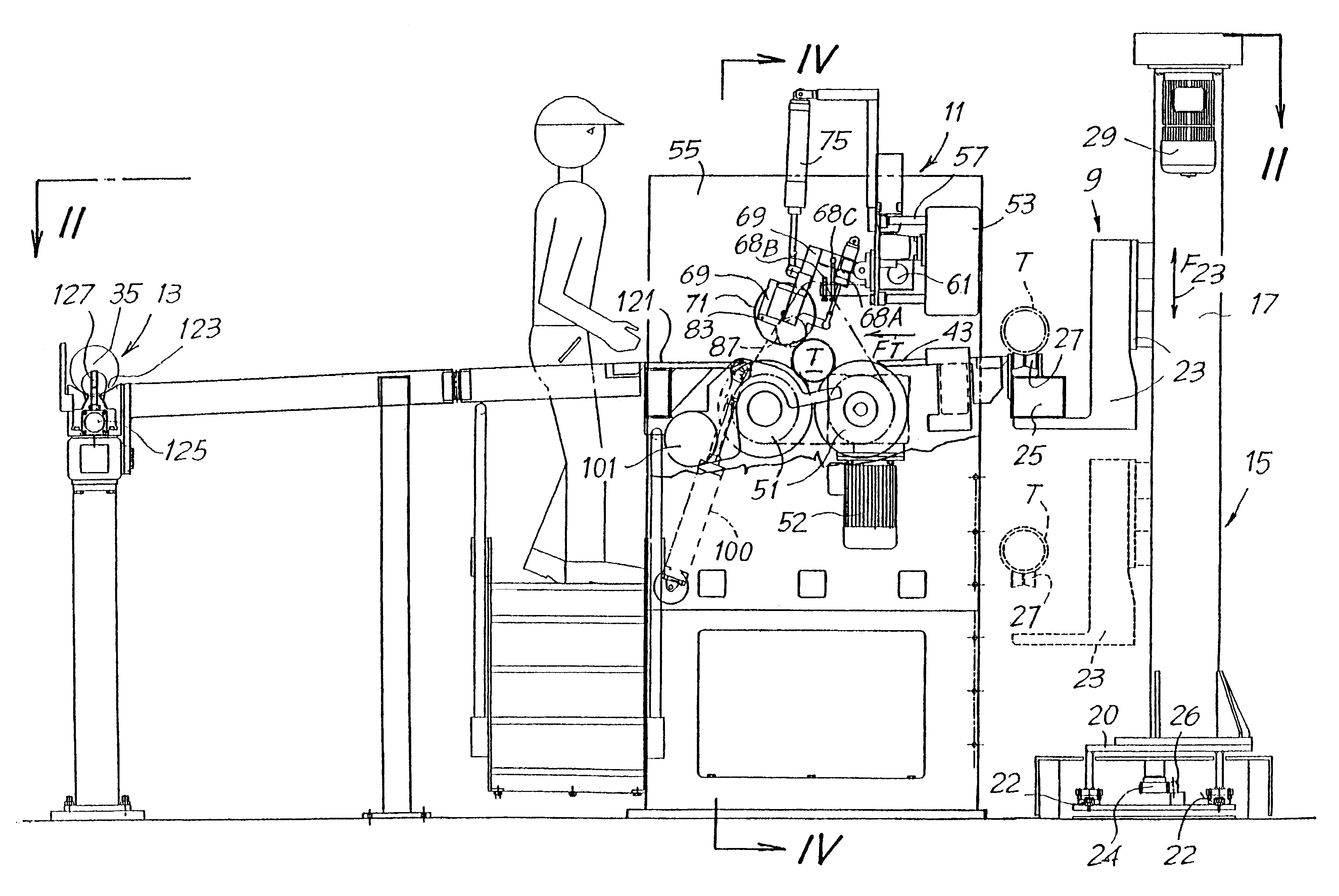
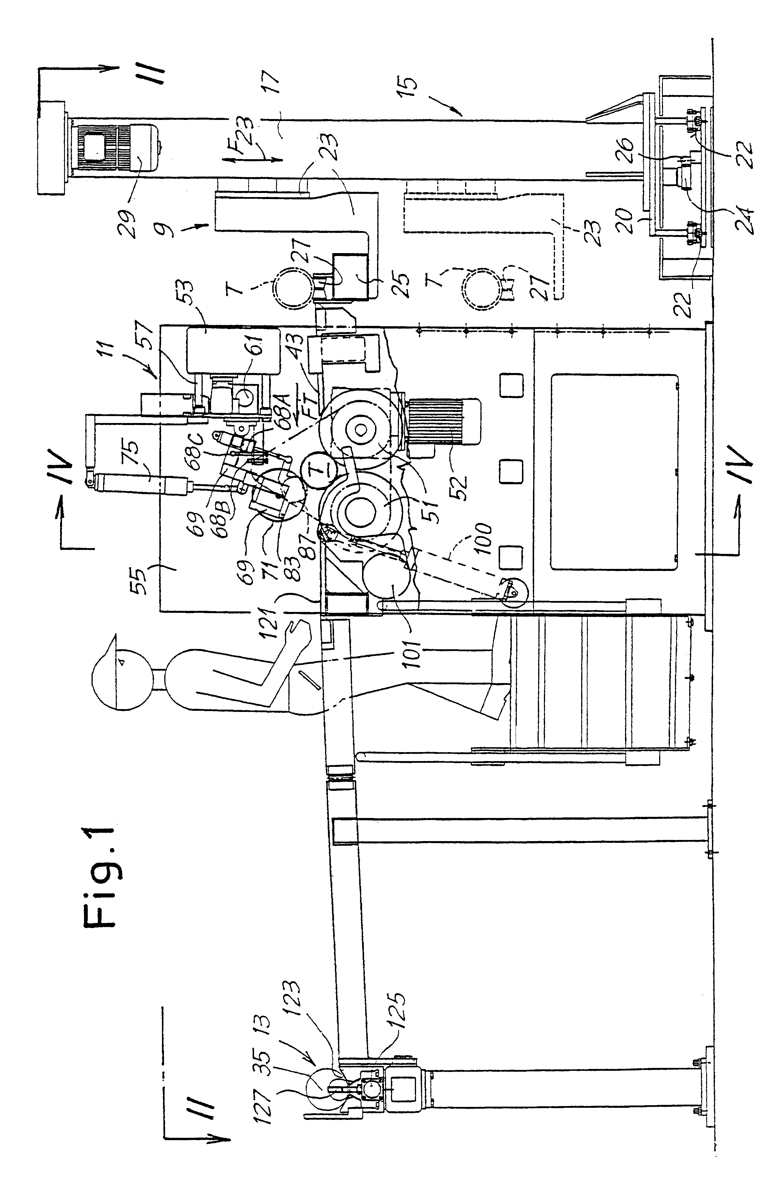
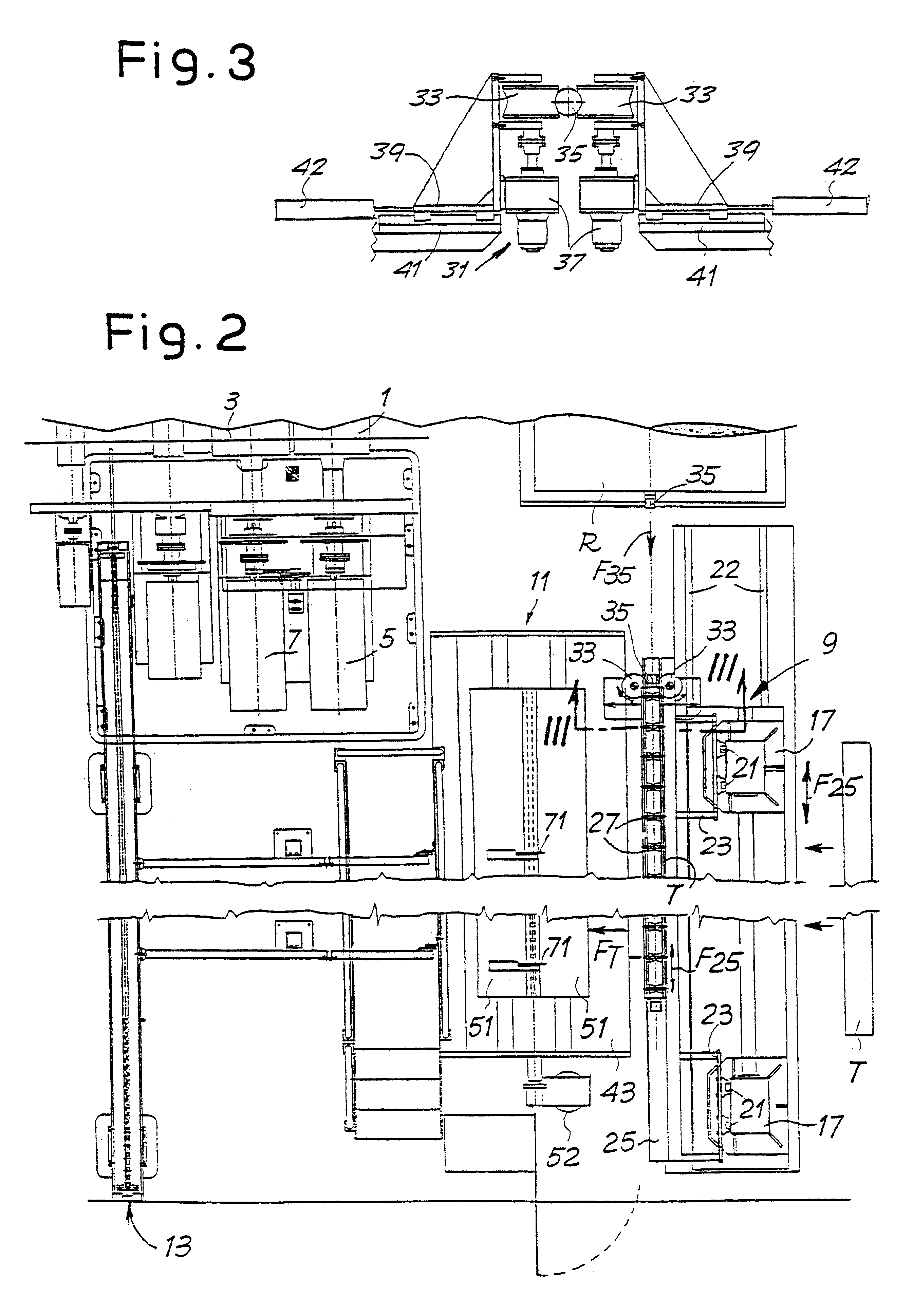
The device according to the invention is placed next to a rewinding or winding machine suitable for operation with expansion mandrels of a known type. In the attached drawing, the only parts of the rewinding machine which are indicated are two lower winding rollers 1 and 3 (see FIG. 2) and corresponding drive motors of the winding rollers, indicated by 5 and 7. The rewinding machine can be of any type, and by way of example it can be of the type described and illustrated in EP-A-0747308. However, it should be understood that the device according to the invention can be used with any winding system in which it is necessary to prepare a plurality of tubular cores on a common mandrel which is subsequently introduced into the winding area of the rewinding machine or other winding machine.

Schematically, the device according to the invention is divided into three stations, which are indicated in a general way by 9, 11 and 13 in FIGS. 1 and 2. The station 9 is a station for extracting the ...


PUM

PropertyMeasurementUnit
Heightaaaaaaaaaa
Trajectoryaaaaaaaaaa
Expansion enthalpyaaaaaaaaaa

Abstract

A description is given of a device for preparing winding mandrels for winding machines or the like, comprising, in combination: an extraction station (9) with an extractor mechanism for extracting a mandrel from one or more rolls of web material and for inserting the extracted mandrel into a tube (T); a cutting station (11) with cutting means (71) for cutting the tube (T) fitted on the mandrel into a set of tubular cores aligned on said mandrel; an insertion station (13) with insertion members (127) for inserting the mandrel with the tubular cores into a winding machine or the like.

Description

The present invention relates to an apparatus for preparing winding mandrels with corresponding tubular winding cores fitted on them for introduction into rewinding machines or other winding machines.STATE OF THE ARTIn various industrial sectors, for example in the paper converting industry, the textile industry and the production of nonwoven textiles, it is frequently necessary to wind on to rolls of smaller or larger diameter a web material taken from a reel of greater diameter. Frequently, a plurality of rolls of smaller height are formed simultaneously by winding strips of web material generated by longitudinally cutting a single strip taken from the reel of greater diameter. The strips are wound on tubular cores adjacent to each other and carried by an expanding winding mandrel. An example of a machine for carrying out this type of winding is described in EP-A-0747308.In some cases, the rolls which are formed simultaneously on the cores fitted on to the mandrel have heights (in...

Claims


Application Information

Patent Timeline
IPC IPC(8): B65H19/30B65H19/12B65H75/22B65H75/24
CPCB65H19/305B65H75/243B65H2301/41828B65H2301/41493B65H2301/41818B65H2301/4148B65H75/2437
Inventor ACCIARI, GIUSEPPE
Owner A CELLI NONWOVENS
Learn More