
Correction of scanning errors in interferometric profiling

a technology of scanning error and interferometer, which is applied in the field of scanning interferometer, can solve the problems of introducing random errors, unambiguous measurement of object shape, and saw-tooth effect following the fringes

Inactive Publication Date: 2003-09-23
BRUKER NANO INC
View PDF5 Cites 32 Cited by
  • Summary
  • Abstract
  • Description
  • Claims
  • Application Information

AI Technical Summary

Problems solved by technology

While scanning through focus, fringes for different parts of the sample surface are produced and analyzed resulting in an unambiguous measurement of the object shape.
However, this is not always the case and the errors in scanning speed influence the final result and need to be accounted for accurate measurements.
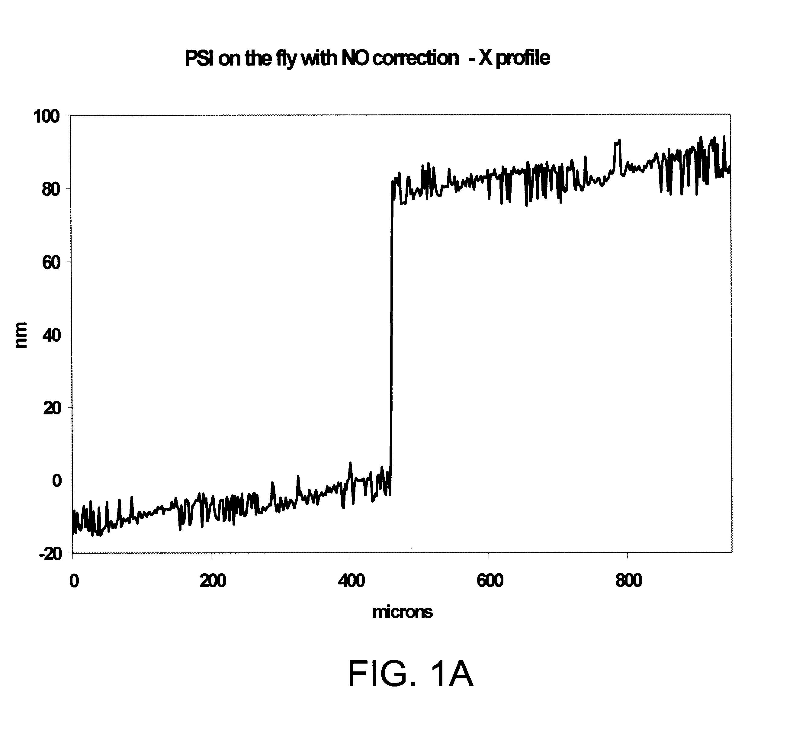
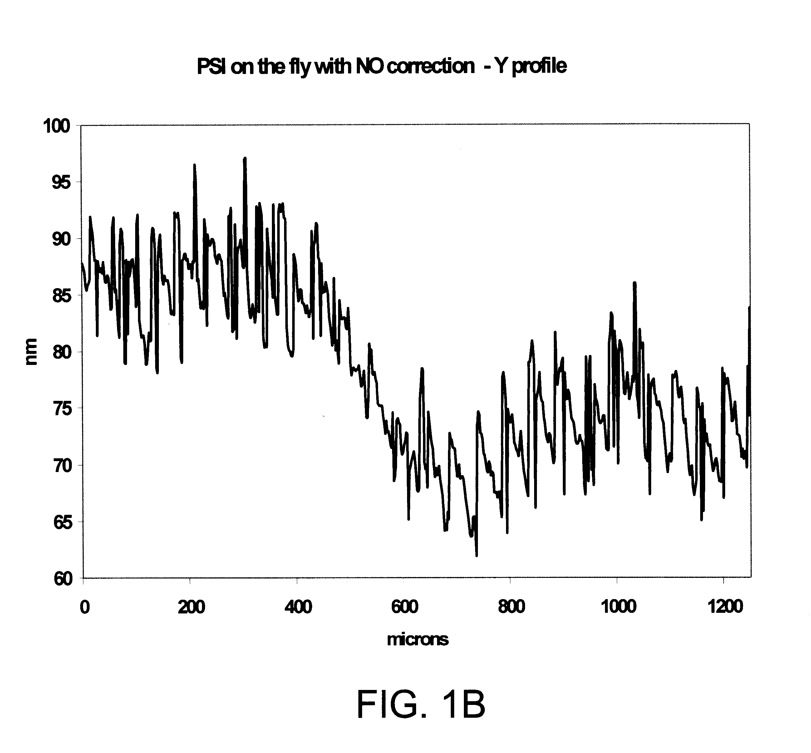
Phase step miscalibration was present, causing saw-tooth effects following the fringes.
Another example of a scanning-error source is high frequency vibrations, which introduce random errors in the intensity values of the interferograms.
Low-frequency vibrations, miscalibration, and nonlinearity in the scanner motion result in erroneous height-difference readings, which may produce ripples, or a saw-tooth profile, or height magnification errors.
In practice, these errors cannot be easily corrected.
In addition, they are usually not repeatable from measurement to measurement; therefore, they are the most difficult errors to correct.
Various studies have characterized the errors associated with scanning perturbations and improved algorithms have been developed to reduce sensitivity to these error sources, but all state-of-the-art corrective techniques require intense calculations that greatly affect processing speed.
The approach produces corrected results that account for scanner nonlinearities, but it requires unwrapping of the phase data and complex post-scan data manipulation.
These requirements prevent utilization of the method on-the-fly and further increase time, storage, and data-processing demands.
This method is direct and fast because it only requires processing of five intensity values at each frame.

Method used


Image

  • Correction of scanning errors in interferometric profiling
  • Correction of scanning errors in interferometric profiling
  • Correction of scanning errors in interferometric profiling

Examples


Embodiment Construction

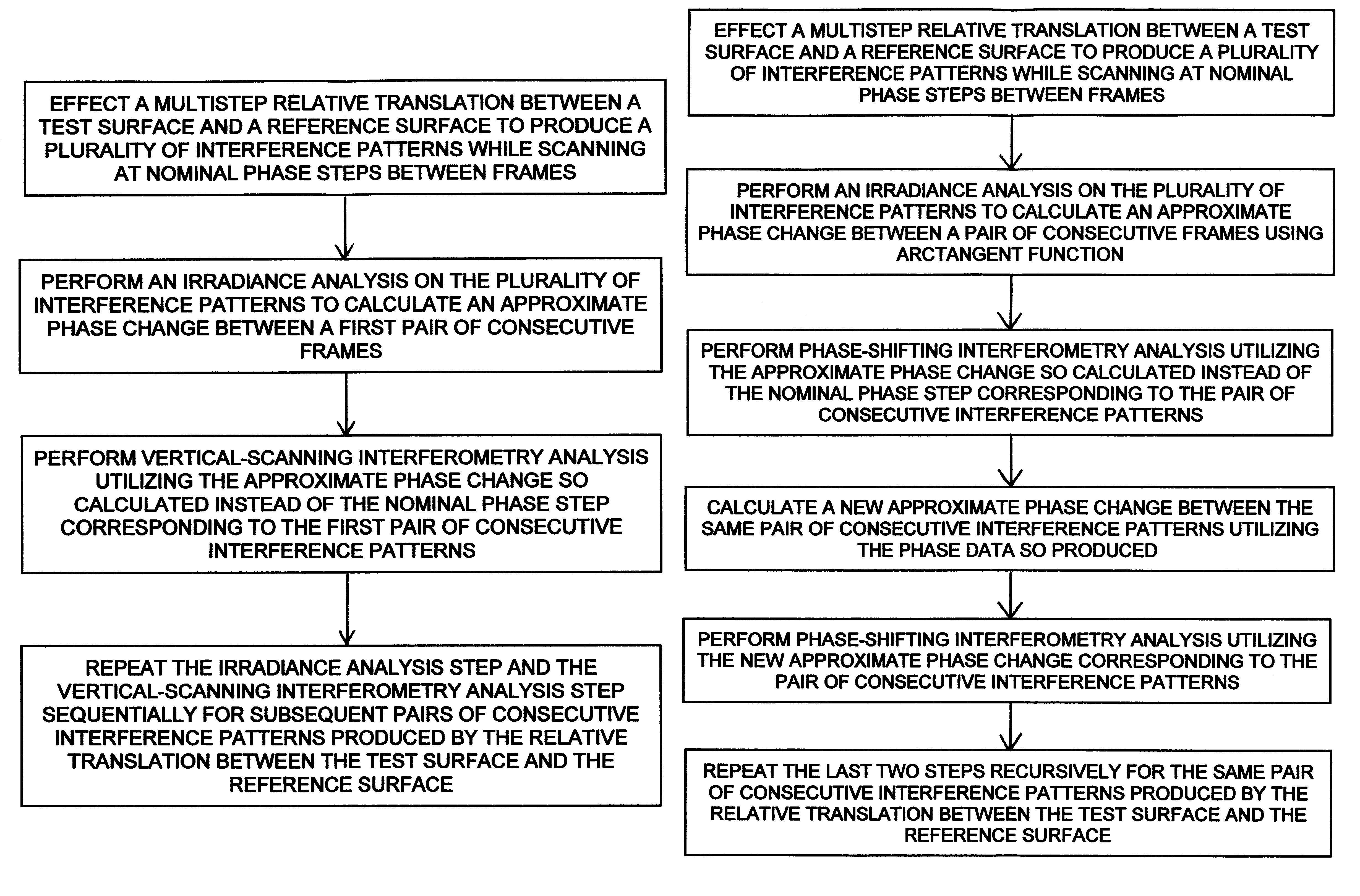
The present invention lies in the realization that scanner errors due to nonlinearities or phase-step miscalibration can be corrected directly and with relatively simple data processing by calculating the exact size of each scan step between successive frames of the correlogram generated by the scan using the same intensity information obtained to produce the height profile of the test surface. By the application of an appropriate algorithm to intensity data gathered during the scan, each step size can be calculated either on-the-fly, or after the scan is completed, and then substituted for the nominal phase step of the scanner to produce a corrected vertical scan-position history.

As used in the art, the term "correlogram" corresponds to the three-dimensional set of interferograms produced by a multistep scan during a conventional interferometric measurement. For the purposes of this disclosure, "nominal" phase step and "nominal" scan step refer to the design phase step and the corr...


PUM


Abstract

Interferometric measurements are carried out in conventional manner to produce a correlogram corresponding to successive scanner steps. An approximation of the actual scan-step size between frames is calculated from multiple-frame intensity data collected around the frame of interest using common irradiance algorithms. The scan-step size so measured is then used in standard PSI, VSI or PSIOTF algorithms, instead of the scanner's nominal phase step. According to one embodiment, the invention utilizes a five-frame PSI algorithm to produce an average scan-step size of four scan steps. According to another embodiment, the phase step between frames is calculated directly utilizing a novel five-frame algorithm that produces an approximation of actual phase step for a given frame, rather than an average value of four steps around the frame. The method requires reduced data processing and can advantageously be applied "on-the fly" as intensity data are acquired during scanning.

Description

1. Field of the InventionThis invention is related in general to the field of scanning interferometry and, in particular, to a novel approach for correcting motion errors in the scanning arm of an interferometer.2. Description of the Related ArtConventional scanning interferometry utilizes a light source, such as white light or a laser beam, to produce interference fringes at a light detector as the optical path difference (OPD) between a test surface and a reference surface is varied during a vertical scan. All measurement techniques based on phase-shifting interferometry (PSI), vertical-scanning interferometry (VSI, also referred to as white-light interferometry), and phase-shifting interferometry on-the-fly (PSIOTF) rely on an analysis of the interference between two beams of light. One beam (the object beam) is reflected from the sample; the other beam (the reference beam) is reflected from the reference mirror; and the two beams are recombined to create an interference pattern ...

Claims


Application Information

Patent Timeline
Patent Type & Authority Patents(United States)
IPC IPC(8): G01B11/24
CPCG01B11/2441
Inventor SCHMIT, JOANNAOLSZAK, ARTUR
Owner BRUKER NANO INC
Learn More