
Combustibility monitor and monitoring method

Inactive Publication Date: 2003-09-23
ORBISPHERE LAB NEUCHATEL
View PDF7 Cites 20 Cited by
  • Summary
  • Abstract
  • Description
  • Claims
  • Application Information

AI Technical Summary

Benefits of technology

Accordingly, a first general object of the present invention are apparatus and method means for monitoring potentially explosive environments (including atmospheres within an essentially enclosed space) while avoiding or minimizing the above mentioned disadvantages of prior art, yet providing economic and completely safe apparatus and method means for continuously analyzing or monitoring mixtures that are potentially
Accordingly, a first object of the invention is an improved method of monitoring potentially explosive environments (including atmospheres within an essentially enclosed space) avoiding the disadvantages of prior art and provide for a reliable and safe test for explosive combustibility of a gas mixture by actually attempting rapid, i.e. explosive combustion in a continuous sequence of test and measuring cycles, each cycle including an actual ignition, and measuring the composition of the gas sample before and after ignition because any combustion of this type will have a most distinct impact upon the composition of the gas mixture contained in the measuring chamber so as to yield reliable and significant data, providing apparatus and method means for continuously analyzing or monitoring gaseous mixtures that are potentially or actually hazardous because of their propensity for very rapid and, sometimes, virtually spontaneous combustion, and which suffer no interference from humidity, nor the presence of oxygen or other impurities typical for a specific field of application.
(b) providing means between the receiving volume and the environment or atmosphere of interest so as to prevent that combustion within the receiving volume will initiate combustion outside the receiving volume and in the environment or atmosphere of interest;
The term "small" with reference to the measuring chamber of the apparatus according to the invention, or with reference to the volume of the receiving space used in the inventive method, is intended to refer to a volume of the chamber or receiving space that is substantially negligible in relation to the volume of the environment or atmosphere of interest outside of, or connected with, the measuring chamber or receiving space. In absolute terms, a typical measuring chamber or receiving space according to the invention has a volume of less than 1 ml, typically about 0.1 ml. so as to minimize the quantity of energy released by combustion of the mixture of reactive components in the measuring chamber or receiving space.

Problems solved by technology

In fact, such explosive combustion would neither be practical in a voluminous chamber nor yield any significant data.
Again, explosive combustion would not be practical nor yield any significant data.

Method used


Image

  • Combustibility monitor and monitoring method
  • Combustibility monitor and monitoring method
  • Combustibility monitor and monitoring method

Examples


first embodiment

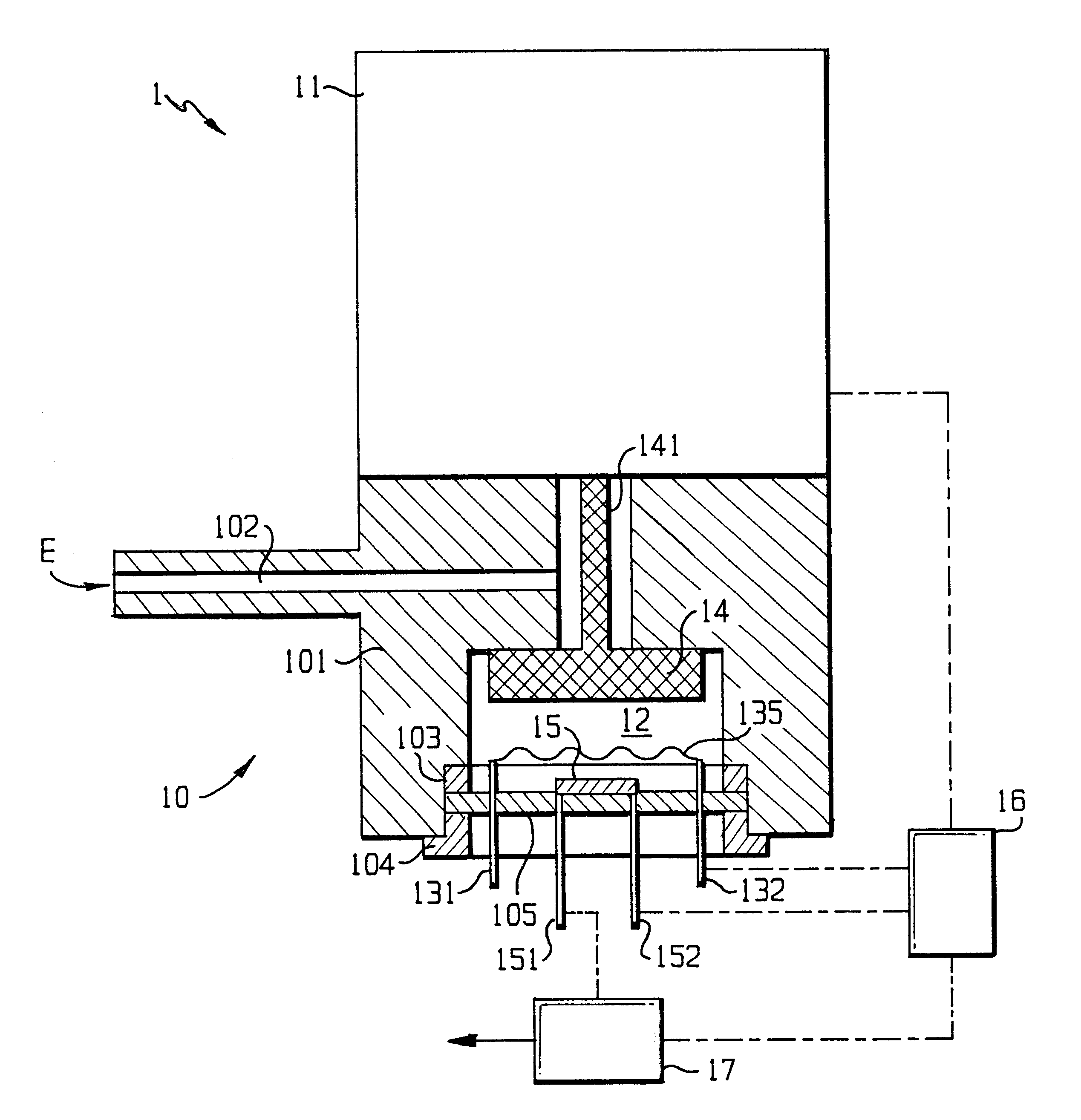
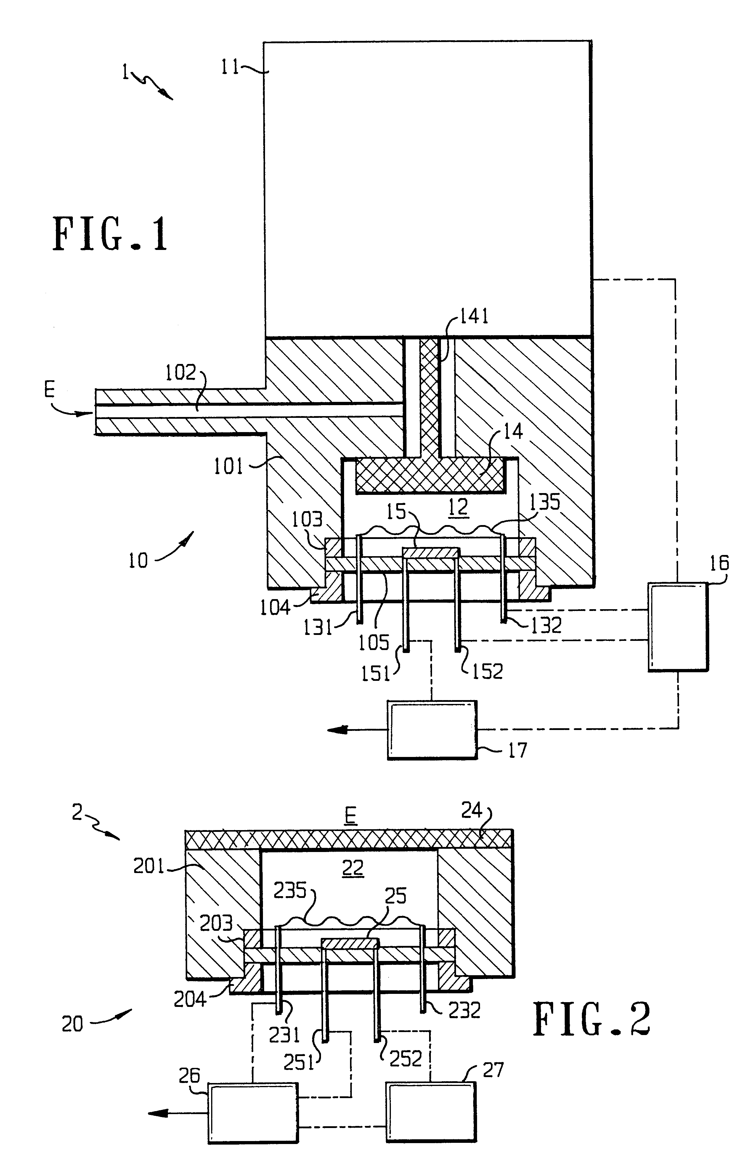
FIG. 1 is a schematic cross sectional view of an apparatus according to the invention;

second embodiment

FIG. 2 is a schematic cross sectional view of an apparatus according to the invention;

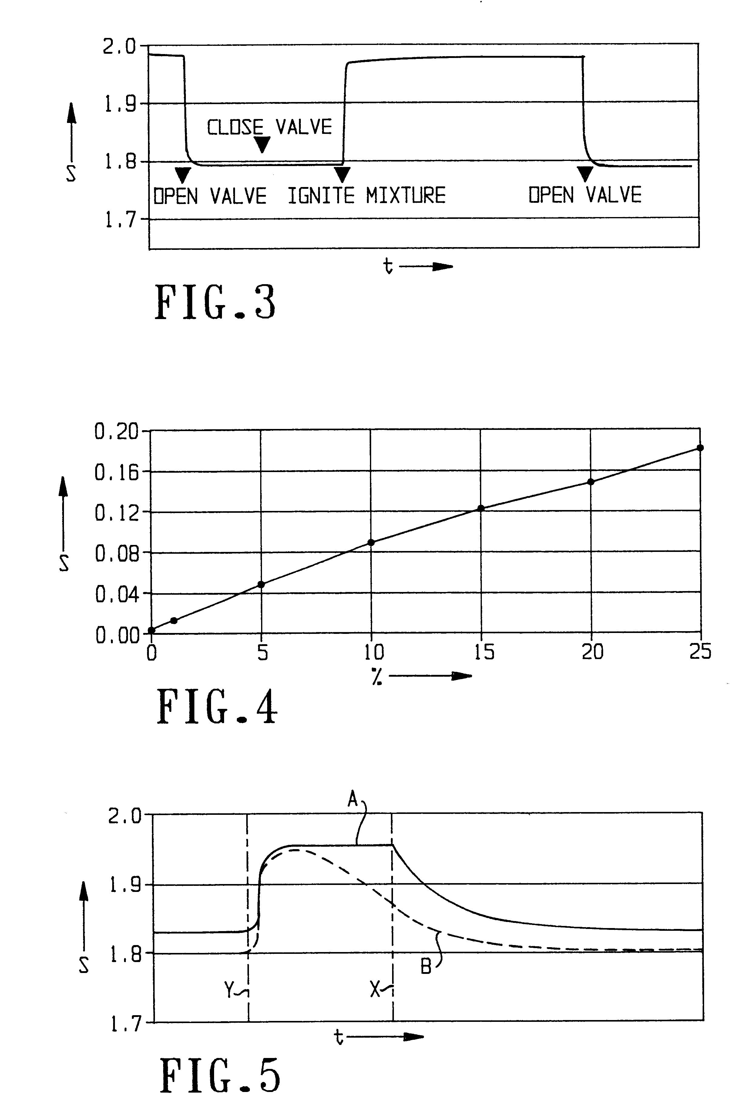
FIG. 3 is a diagram illustrating an example of a cycle when operating the method according to the invention;

FIG. 4 is a diagram illustrating signal strength as a function of concentration of a critical first component when operating an embodiment of the inventive method;

FIG. 5 is a diagram illustrating signal curves for different concentrations of a critical first component when operating another embodiment of the inventive method;

third embodiment

FIG. 6 is a schematic cross sectional view of an apparatus according to the invention for measuring by means of a pulsing method of operation;

FIG. 7 is a diagram illustrating signal evolution when measuring by means of a pulsing method using a flushing gas; and

FIG. 8 is a diagram showing signal change when monitoring hydrogen in relation to its partial pressure in an atmosphere containing nitrogen and helium as additional components.

DETAILED EXPLANATION OF THE DRAWINGS

FIG. 1 is a diagrammatic illustration of an apparatus 1 according to the invention connected via a conduit 102 with an environment E, e.g. the atmosphere contained in an enclosed space (not shown) potentially or effectively containing a gas, e.g. hydrogen, that would form a combustible mixture with the oxygen that is normally present within or outside of an enclosed space which is of analytical interest because it requires continuous monitoring.

Reaction chamber 12 is provided with flame arrestor in the form of a valve ...


PUM


Abstract

An apparatus (1) for determining the concentration of a critical first component, such as hydrogen, of an atmosphere or environment (E), wherein the first component is capable of forming a combustible mixture with a second component, such as oxygen; the apparatus comprises: (A) a sampling unit (10) including: (A1) a small measuring chamber (12) operatively connected with an ignition means (135) capable of being operated so as to initiate in said chamber a combustion of said critical first component by reaction with said second component, and (A2) at least one sensor (15) operatively connected with said measuring chamber for generating a signal formed by essentially proportionate contributions from all significant components contained in said measuring chamber; (B) at least one flame arrestor (14) intervening between said measuring chamber (12) and aid environment (E) of interest; and (C) a control unit (16) capable of imposing a mode of operation in at least two distinct phases wherein, during a first phase, said environment of interest is allowed to accumulate in said measuring chamber; and wherein, during a second phase, said ignition means is operated for initiating said combustion in said chamber; and (D) a means (17) for evaluating at least one signal generated by said at least one sensor before operation of said ignition means, and at least one signal generated by said at least one sensor after operation of said ignition means so as to generate a signal (S) which is indicative of said concentration of said critical first component in said environment of interest.

Description

The present invention generally relates to analysis of potentially hazardous mixtures of substances and specifically to apparatus and method means for combustibility monitoring by determining the concentration of a first critical component in an environment or atmosphere of interest containing a second component that is capable of forming a combustible mixture with the critical first component. The invention is of particular relevance for monitoring gaseous substances and atmospheres containing them.Combustible gaseous mixtures are those in which a first gaseous component thereof is capable of rapid exothermic reaction with a second component of the mixture by an oxidative process which may, but need not, involve oxygen as the oxidizing agent. Depending upon the relative amounts of the reacting components, the speed of reactions, the amount of heat generated, and the activation required for initiation of the reaction, such mixtures may cause substantial hazards.Consequently, prevent...

Claims


Application Information

Patent Timeline
IPC IPC(8): G01N27/14G01N27/16G01N27/18G01N33/00G01N33/22
CPCG01N27/16
Inventor HALE, JOHN MARTINSTEHLE, GERARD ROLANDSERRATORE, DOMINIQUEWEBER, EUGEN
Owner ORBISPHERE LAB NEUCHATEL
Learn More