Racquet with slidable weight
a slidable, racket technology, applied in the field of rackets, can solve the problems of inferior maneuverability of the racket, the risk of destroying the cylinder body, and the loss of rebounding force of the ball being hit by the rack
Inactive Publication Date: 2003-09-23
BRIDGESTONE SPORTS
View PDF13 Cites 14 Cited by
- Summary
- Abstract
- Description
- Claims
- Application Information
AI Technical Summary
Benefits of technology
According to this tennis racket, when a player swings the racket horizontally, the centrifugal force carries the water within the pipe in the direction of the racket tip, making the racket in a state of top heavy. On the other hand, when the racket is stood up vertically as in the case of hitting volleys, the water remains around the grip, leaving the racket tip relatively lighter, thus lightens the swing itself.
Under such circumstances, an object of the present invention is to overcome aforementioned problems, and to achieve a goal described hereinafter. The object of the present invention is to provide a racket, specifically a tennis racket devised to striking back strong balls by an increased moment of inertia, which demonstrates a smooth shift in the center of gravity of the racket during the swing.
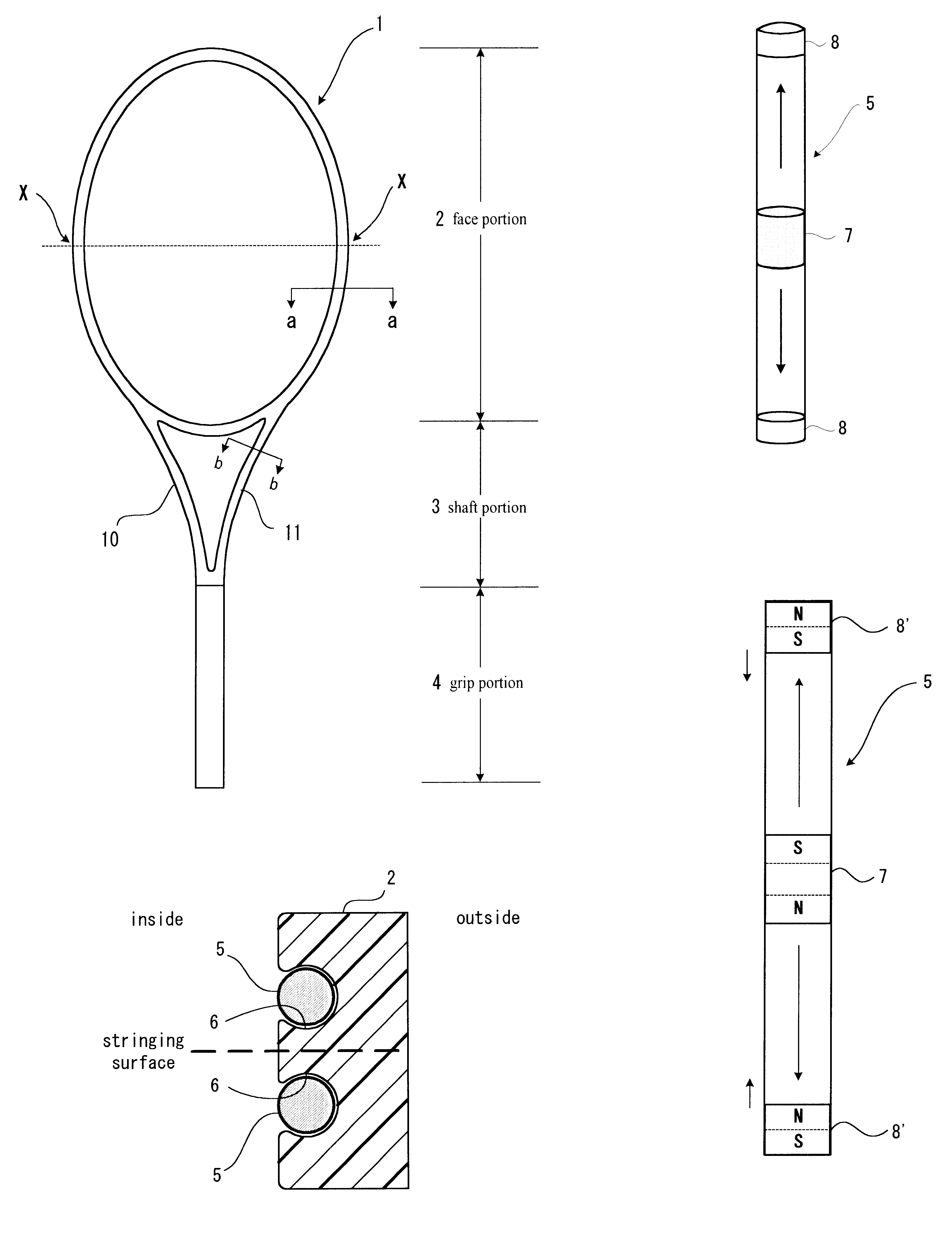
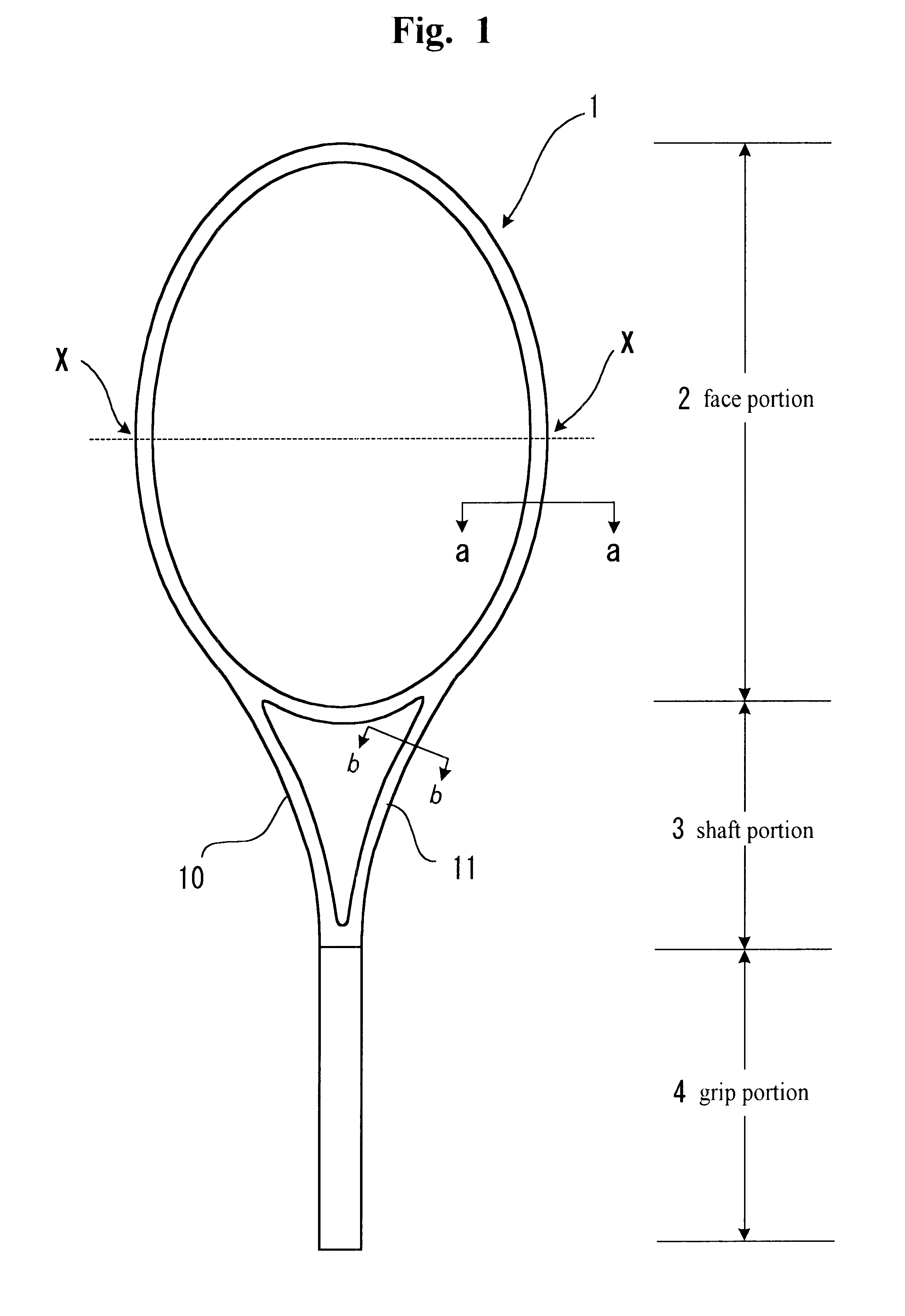
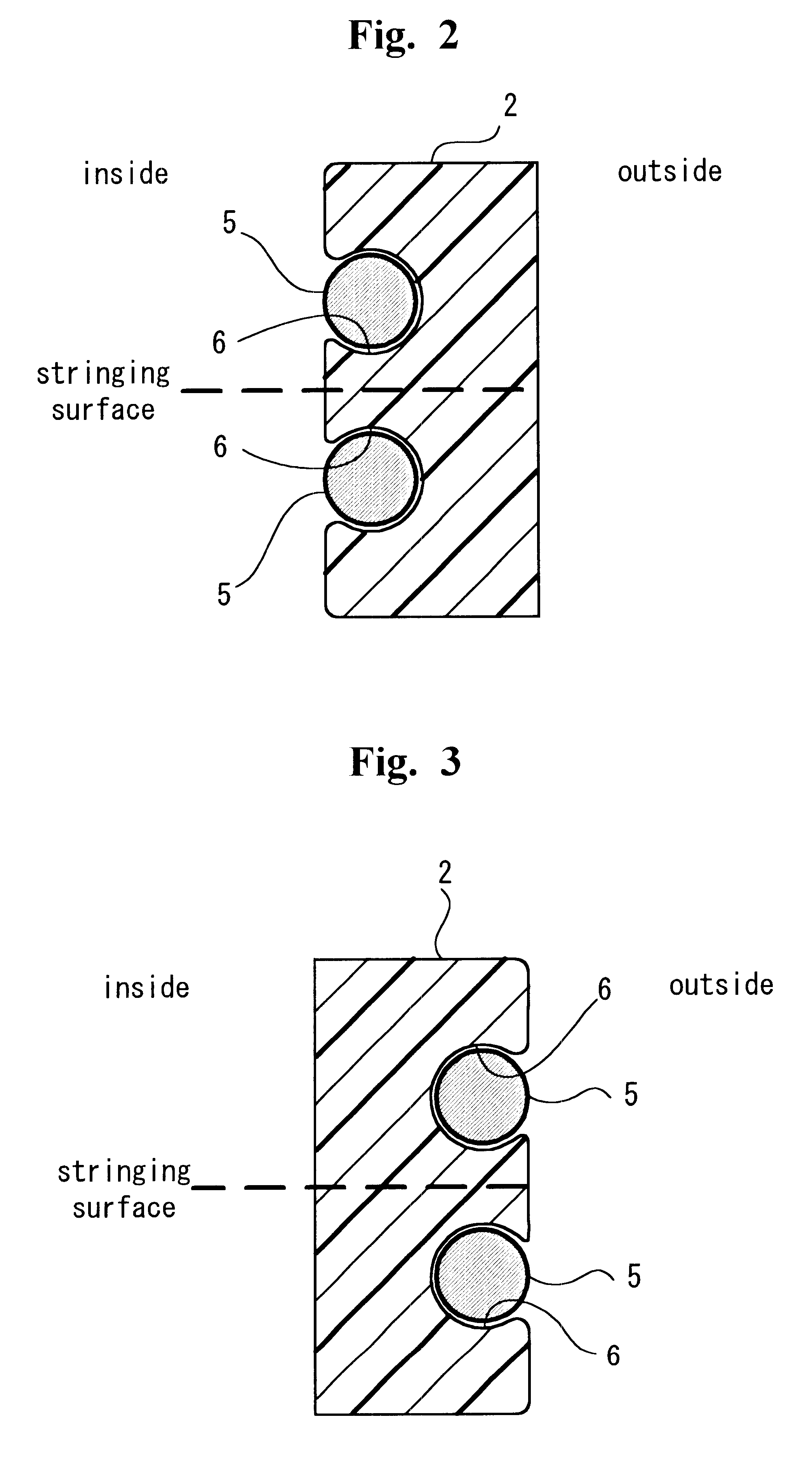
According to the present invention, the racket is used for use in badminton, squash, or preferably tennis and is capable of striking strong balls, and demonstrating outstanding increase in the moment of inertia is provided which comprises a groove adjusted in the shape and length of a tube which encloses a lead of predetermined length, provided in two portions covering the points of maximum width of a frame comprising a face portion. By embedding the tube in the groove so that the outer surface of the tube does not exceed the outer surface of the frame, or in other words, the tube is disposed in the groove so that it does not protrude from the surface of the frame. The present invention allows the lead to smoothly slide in the direction of the racket tip when the centrifugal force is exerted to the racket, and to smoothly slide downward in the direction of the grip by the force of gravity when the racket is stood upwards.
Problems solved by technology
However, by using the racket disclosed in JP-A 63-318966, there is a risk of destroying the cylinder body by accidental contact with a ball, when cylinder body enclosing a balancer is disposed along the inner circumference of the face portion of the racket frame.
Also, because the cylinder body restrains the motion of the stringing (i.e., interferes with the stringing) provided within the inner circumference of the face portion, there is a risk of losing rebounding force of the ball being hit by the racket.
On the other hand, when the cylinder body is disposed on the outer circumference of the face portion of the frame, there is a risk of damaging the cylinder body by accidental impact with the ground in an attempt to strike back low balls, or disturbs the swing, which leads to inferior maneuverability of the racket.
A racket disclosed in JP-U 4-27953 may exhibit uncomfortable feeling of use during the swing when tapping noise of the water injected in the pipe caused by leaving out some air spaces within the pipe moves inside the frame, leading to plurality of water surfaces existing in the pipe.
Further, when the racket is rapidly shaken, air lumps are decoupled in many minute air bubbles, and since the moving resistance of the bubble in water is extremely large, causes the motion of the bubbles to slow down, which generates slow movement in the center of gravity when the racket is shaken.
On the other hand, when the length of the groove (tube) is defined too short, the center of gravity is restricted from shifting enough, which could degrade the performance of the racket.
When the diameter of the tube is too large, in addition to the fact that the tube cannot be disposed within the frame, the formation of the frame becomes difficult and will lead to deterioration of the strength of the frame.
On the other hand, when the diameter of the tube is too small, there is a risk of sacrificing a sufficient weight shift effect of the weight enclosed in the tube adjusted to the size of the tube.
When the weight of the weights are too light, the weight shift effect is inferior.
On the other hand, when the weight of the weights are too large, the distance of the weight shift is short.
Method used
View moreImage
Smart ImageViewing Examples

Examples
first embodiment
Using the racket of the first embodiment, the groove in the length of 90 mm (approximately 3.54 inches)was provided at the frame comprising a face portion, within the groove, a tube in the length of 88 mm (approximately 3.46 inches) (equal to 9.0% of the entire circumference of the frame) made of polyethylene was embedded as shown in FIG. 2. The tube was fixedly adhered to the groove by an adhesive.
Login to View More PUM
 Abstract
A racket comprising a frame body having a face portion, a shaft portion, and a grip portion, and a groove in the length of 10% to 20% against the entire circumference of the frame comprising the face portion provided at two portions covering maximum width points of the frame comprising the face portion and a closed tube enclosing a slidable weight weighing 2 g to 10 g is embedded in the groove.
Description
The present invention relates to a racket used in sport events such as tennis, badminton, and squash (or formally a squash racquets), and more particularly to a racket capable of striking strong balls by an increased moment of inertia effectuated by moving the center of gravity in the direction of racket head (or racket tip) at the time of the swing.DESCRIPTION OF THE RELATED ARTThere have been various inventions disclosed conventionally for rackets which are capable of shifting their center of gravities in the direction of the racket heads. Such inventions include rackets disclosed in JP-A (Japanese Patent Application Laid-Open) No. 63-318966, 64-40071, and JP-U (Japanese Utility Model Application Laid-Open) No. 04-870, and 04-27953.For instance, JP-A 63-318966 discloses a racket which disposes narrow tubes or narrow holes along the stringing frame and the neck portion, within which a moving body is inserted in a state to move around freely. At the time of swinging the racket stron...
Claims
Login to View More Application Information
Patent Timeline
 IPC IPC(8): A63B49/04A63B49/00A63B49/02A63B59/00A63B49/10A63B60/02A63B60/04A63B60/52A63B102/02A63B102/04A63B102/06
CPCA63B49/00A63B49/04A63B59/0096A63B59/0092A63B60/02A63B60/04A63B60/54A63B49/12A63B60/08A63B60/14
Inventor MATSUOKA, TOYOTAKESHIRAI, SATOSHI
Owner BRIDGESTONE SPORTS
Features
- R&D
- Intellectual Property
- Life Sciences
- Materials
- Tech Scout
- Unparalleled Data Quality
- Higher Quality Content
- 60% Fewer Hallucinations
Learn More Browse by: Latest US Patents, China's latest patents, Technical Efficacy Thesaurus, Application Domain, Technology Topic, Popular Technical Reports.
© 2025 PatSnap. All rights reserved.Legal|Privacy policy|Modern Slavery Act Transparency Statement|Sitemap|About US| Contact US: help@patsnap.com