Non-contact servo track writing apparatus and method

a writing apparatus and non-contact technology, applied in the direction of instruments, data recording, track finding/aligning, etc., can solve the problems of large size of the entire hard disk mechanism, difficult to attach a retro-reflector thereto, and small arm for positioning the write head, etc., to achieve easy adaptation, easy production, and easy to adapt to the production environment of the disk drive

Inactive Publication Date: 2003-08-05
EXCEL PRECISION
View PDF9 Cites 12 Cited by
  • Summary
  • Abstract
  • Description
  • Claims
  • Application Information

AI Technical Summary

Benefits of technology

An advantage of the present invention is that it retains the accuracy of conventional laser interferometer head positioning devices.
A further advantage of the present invention is that it can be used with very small head positioning arms and very small magnetic media disks.
Yet another advantage of the present invention is that it is not necessary to mechanically connect an...

Problems solved by technology

With such very small media disks, not only is it increasingly critical that the servo tracks be accurately placed (since the actual physical track density is increased as the size of the media is decreased) the problem is also introduced that an arm for positioning the write head must be so small that it is difficult to attach a retro-reflector thereto.
Furthermore, the entire hard disk mechanism is so small that it is not possible to introduce any bulky equipment into the area of the servo writing mechanism to position the arm.
At the time of the inventor's prior application no prior art device was readily adaptable to control very small positioning arms while providing the same degree of accuracy found in direct reading interferometers having the retro-reflector mou...

Method used


Image

  • Non-contact servo track writing apparatus and method
  • Non-contact servo track writing apparatus and method
  • Non-contact servo track writing apparatus and method

Examples


Embodiment Construction

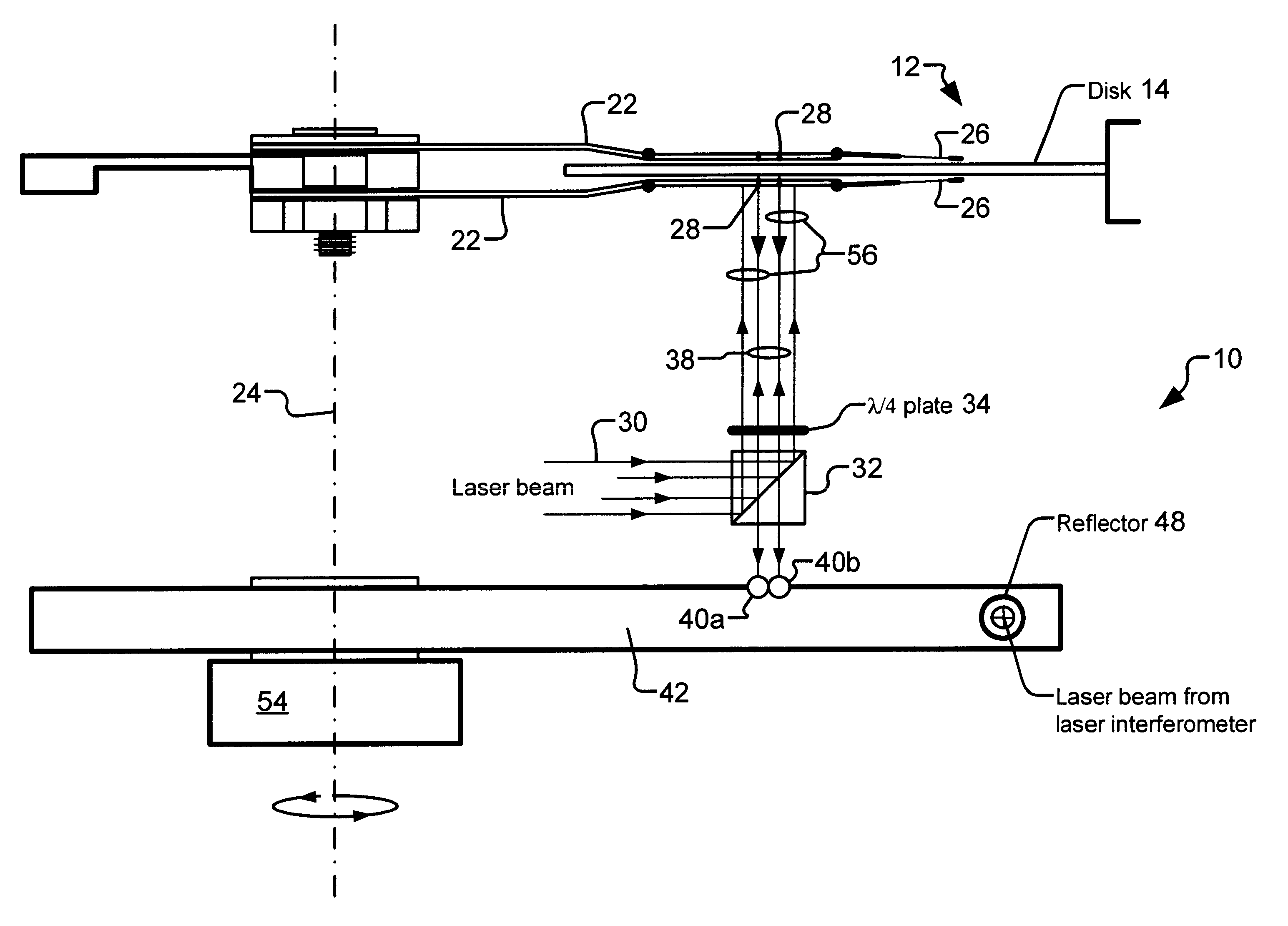
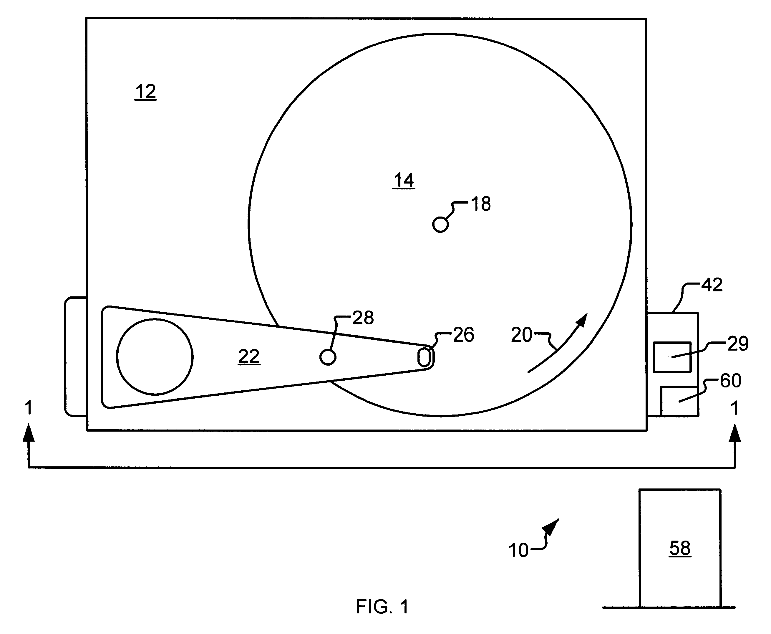
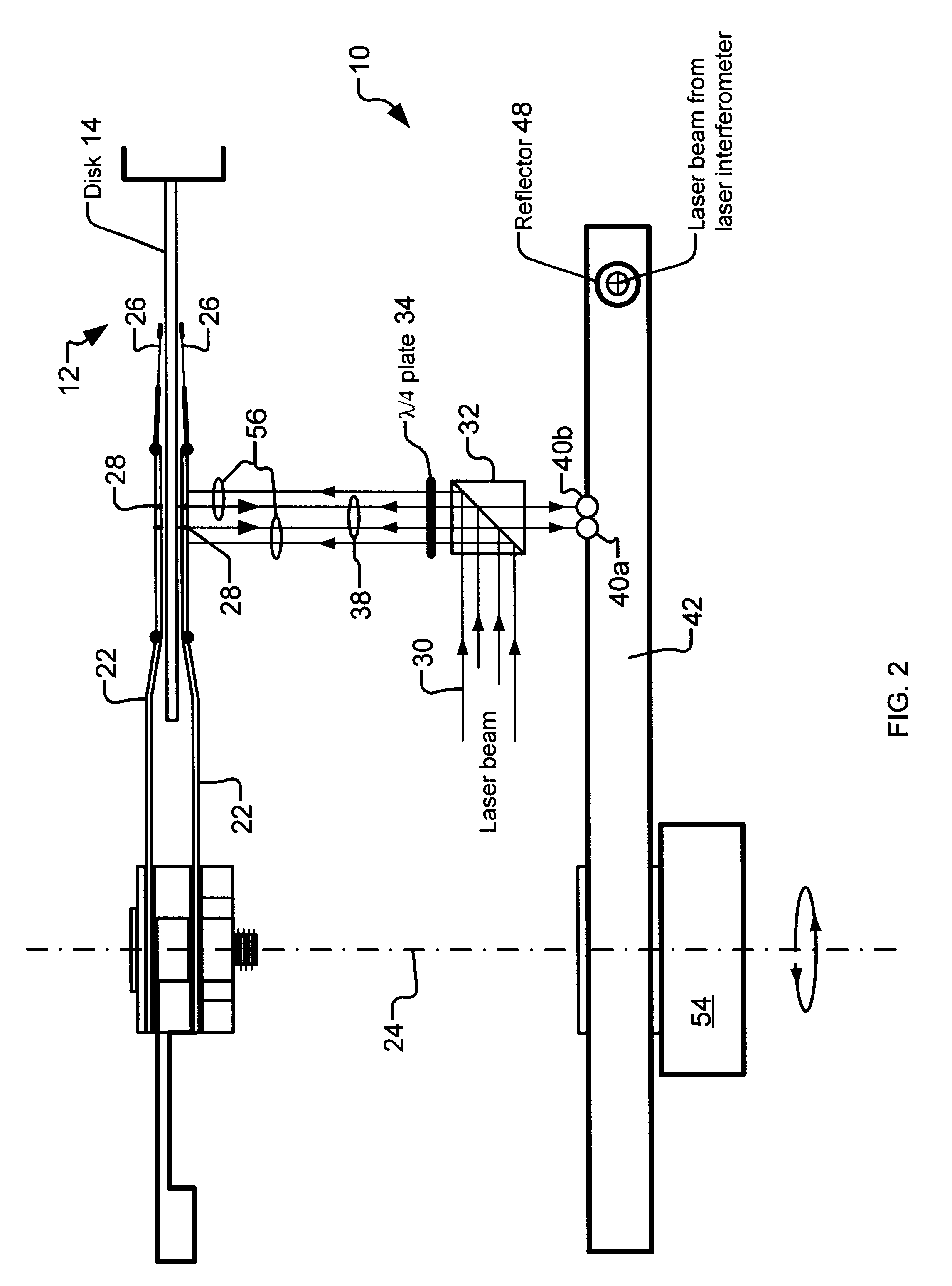
The best presently known mode for carrying out the invention is a servo track writing apparatus for use on rotating magnetic media "hard disk drives." The predominant expected usage of the inventive servo track writing apparatus is in the computer equipment manufacturing industry, particularly in manufacture of very small such hard disk drives, wherein the ability to accurately locate a head positioning arm without introducing bulky devices into the disk drive is desirable.

The servo track writing apparatus of the presently preferred embodiment of the invention is illustrated in a top view in FIG. 1 and in side view in FIG. 2 (omitting non pertinent elements, like the workpiece housing), and is designated therein by the general reference character 10. The servo track writing apparatus 10 has as a disk drive assembly 12 with a media disk 14 upon which a servo track 16 (not shown, servo tracks are not physically visible) is to be written. The media disk 14 is caused to spin about a dis...


PUM


Abstract

A servo track writing apparatus (10) for writing servo tracks (16) on a media disk (14) of a disk drive assembly (12) having a Positioning arm (22) with a through hole (28) therein. The writing apparatus (10) has a laser source (29) which directs a source beam (30) through a polarizing beam splitter (32) and a quarter-wave plate (34) to either pass through the through hole (28) and reflect off of the media disk (14) as a reflected beam (38), or to be reflected from regions of the positioning arm (22) proximate to the through hole (28) as a reflected beam (56). The writing apparatus (10) further has a remote tracking arm (42) with two photodiodes (40a, 40b) suitably mounted thereon to receive the reflected beams (38, 56). The tracking arm (42) is caused by a motive means (54) to precisely track the positioning arm (22) of the disk drive assembly (12). A laser interferometer (58) is then used to detect an optical target (60) mounted on the tracking arm (42) and determine positioning for writing of the servo track (16).

Description

The present invention relates generally to the field of laser interferometry and more particularly to an improved system for accurately positioning a mechanical arm using a laser interferometer. The predominant current usage of the non-contact servo track writing apparatus is in the positioning of servo track writing heads in the manufacture of very small computer hard disk drives.When manufacturing computer hard disk drives it is necessary to magnetically "write" servo tracks on the disks, which servo tracks constitute the references from which other positions on the disks are located. Given the very high track density of modem hard disk media, it is critical that these servo tracks be accurately located and, therefore, it is necessary to position the servo track writing apparatus over the disk as precisely as possible during this process. Laser interferometry has been widely used in this endeavor due to the high resolution, high repeatability, great accuracy and fast signal updati...

Claims


Application Information

Patent Timeline
IPC IPC(8): G11B5/596
CPCG11B5/59633
Inventor TSAI, JOHN C.
Owner EXCEL PRECISION
Why Eureka
Try Eureka