
Birefringent reflectors using isotropic materials and form birefringence

a technology of isotropic materials and reflectors, applied in the field of reflectors, can solve the problems of difficult to meet certain stringent flatness specifications, processing techniques and/or polymeric materials, and difficulty in making low film volumes economically

Inactive Publication Date: 2003-07-08
3M INNOVATIVE PROPERTIES CO
View PDF55 Cites 121 Cited by
  • Summary
  • Abstract
  • Description
  • Claims
  • Application Information

AI Technical Summary

Benefits of technology

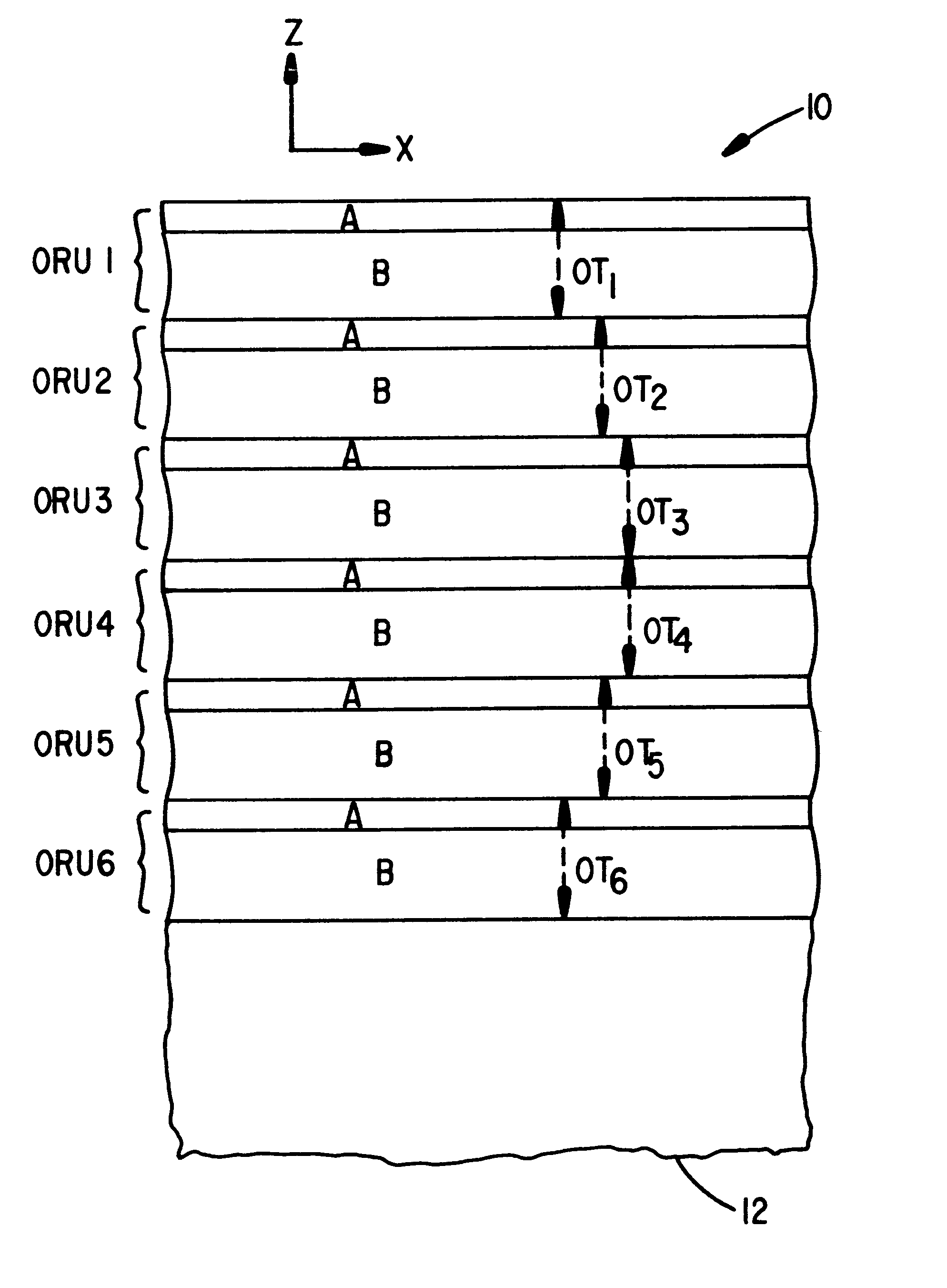
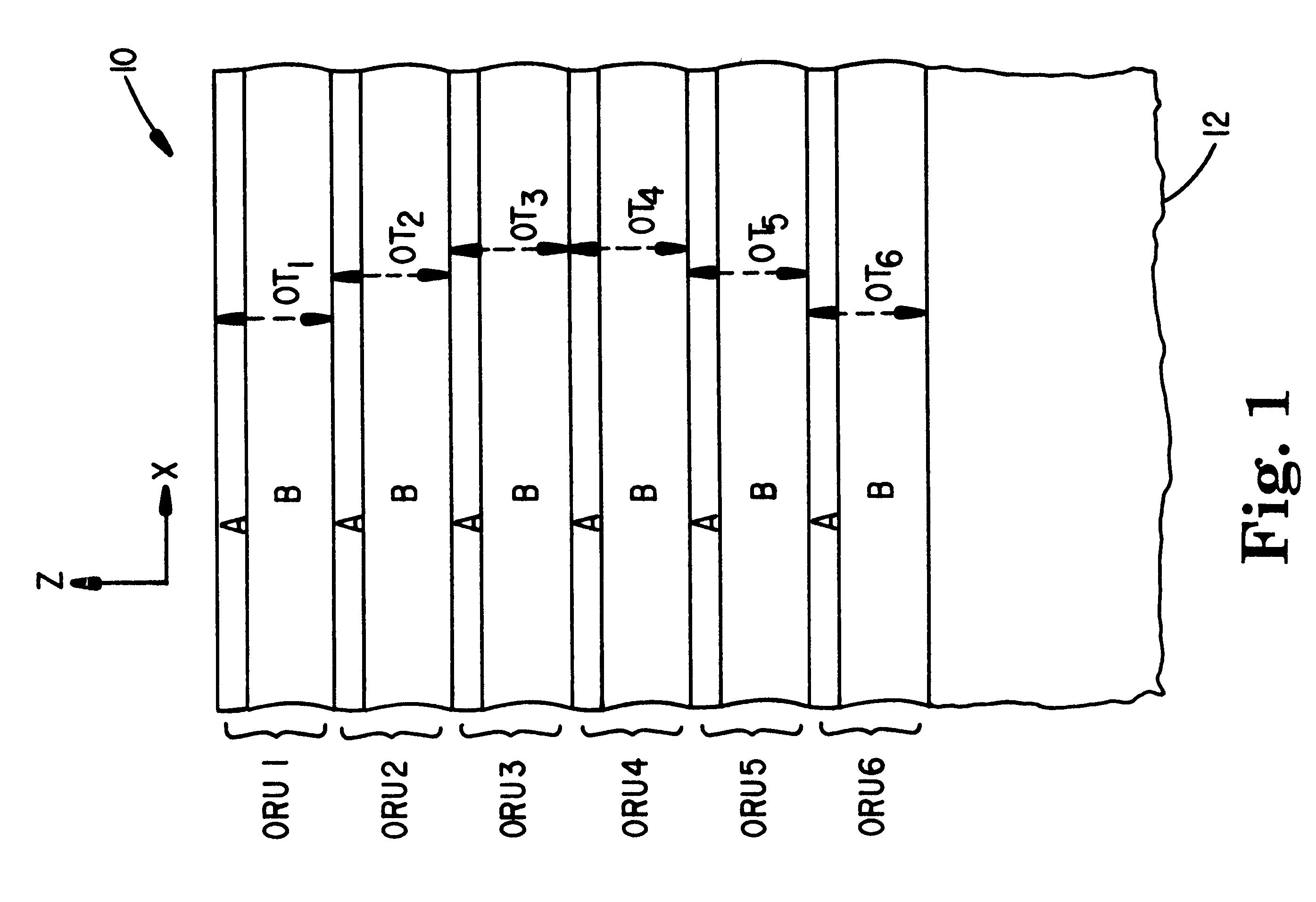
Disclosed herein are reflectors such as mirrors or reflective polarizers that comprise a plurality of thin film optical repeat units to achieve reflection or transmission of light as a function of wavelength, polarization state, and direction of incidence. The reflectors include in a plurality of the optical repeat units at least one optical layer that is form birefringent. Further, the form birefringent layer and another optical layer in the optical repeat units have z-indices that are tailored to produce a desired optical effect as a function of incidence angle. Someti

Problems solved by technology

However, the processing techniques and / or polymeric materials also have inherent disadvantages in certain other respects, such as difficulty in making low volumes of the film economically, difficulty meeting certain stringent flatness specifications, and difficulty surviving in applications where the film is exposed to substantial amounts of ultraviolet light or to temperatures above about 200 degrees C. High angularity reflective films that avoid one or more of these difficulties would be highly useful in a variety of applications.
However, the benefits of using such form birefringent materials in high angularity reflective films, where the z-index of adjacent layers is tailored to achieve a desired angular behavior in the reflection or transmission of a polarizer or mirror, have not been taught or appreciated by others.

Method used


Image

  • Birefringent reflectors using isotropic materials and form birefringence
  • Birefringent reflectors using isotropic materials and form birefringence
  • Birefringent reflectors using isotropic materials and form birefringence

Examples


example 1

Mirror Film Having 16 Microlayer Negative Unaxial Optical Layers Alternating with Isotropic Optical Layers

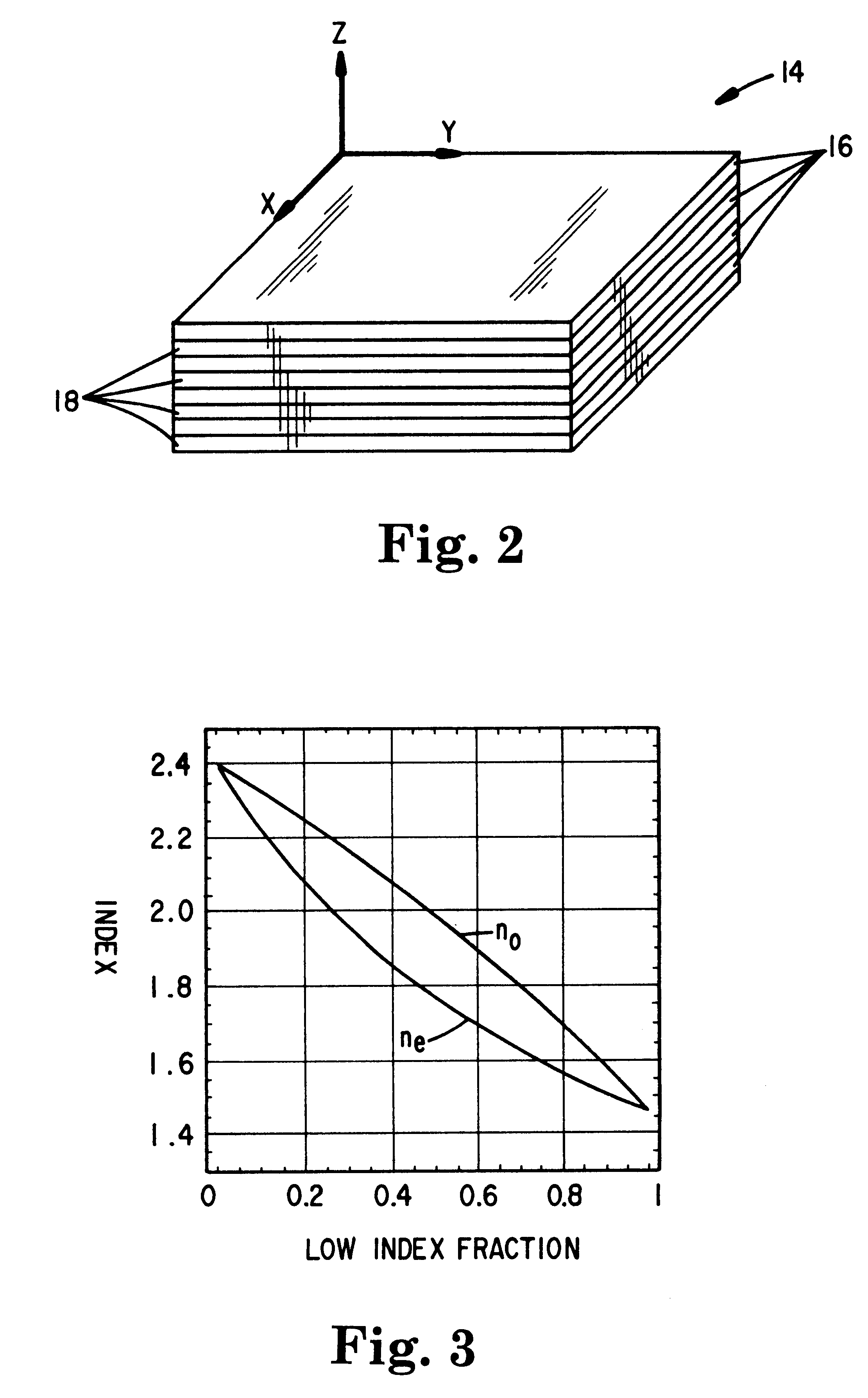
In this first example, 8 pairs or 16 microlayers total were used in each 1 / 4 wave form birefringent optical layer. The microlayers, with indices of 1.46 and 2.4, thus have thicknesses of about 6.88 and 8.12 nm respectively. This corresponds to a low index material fraction of about 0.46. The effective indices of this composite layer are approximately 2.04 (in-plane) and 1.80 (out-of-plane). This form birefringent layer alternates with a 126 nm thick isotropic optical layer of index 1.82. The stack is immersed in a 1.70 index medium. FIG. 11 shows the calculated transmission spectra at normal incidence (curve 38) and at 45.degree. for s- and p-polarized light (curves 40 and 42, respectively).

Note in FIG. 11 that the fractional bandwidth and peak height for p-polarized light is the substantially the same at 45 degrees as at normal incidence in a high index medium of index 1.7. For...

example 2

Another Mirror Film Having 16 Microlayer Negative Uniaxial Optical Layers Alternating with Isotropic Optical Layers

The left bandedges of s- and p-polarized light in FIG. 11 can be brought into closer coincidence by an adjustment in the refractive index of the intermediate index material. This Example 2 mirror film therefore was of the identical construction as the Example 1 film, except that the refractive index of the isotropic optical layer was changed from 1.82 to 1.77. FIG. 13 shows the resulting spectra, where curve 44 is for normally incident light, and curves 46,48 are for s- and p-polarized light respectively that is incident on the mirror film at 45.degree.. The normal incidence and s-polarization reflectivities are stronger due to the larger in-plane index difference (2.04-1.77 versus 2.04-1.82). The p-polarization band is slightly weakened because of the deviation from the z-matched condition in the direction of isotropic stacks. Instead of changing the intermediate index...

example 3

Mirror Film Having 4 Microlayer Negative Uniaxial Optical Layers Alternating with Isotropic Optical Layers

In Example 3, the number of microlayers are reduced even further. This multilayer mirror film was of the same construction as that of Example 1, except the form birefringent optical layers each consisted of only 2 pairs, or 4 microlayers. The microlayers were four times as thick as those of Example 1, thus maintaining the low index fraction of 0.46. The thickness of the isotropic optical layers was maintained at 126 nm, and the index maintained at 1.82. With this construction, the spectra of FIG. 14 are obtained. Curve 50 is for normally incident light, and curves 52,54 are for s- and p-polarized light respectively that is incident on the mirror film at 45.degree.. As seen, the p-polarization reflectance band is slightly narrower, and the left bandedges for s and p-polarized light are substantially aligned. The weaker p-polarization reflectance compared to FIGS. 11 or 13 indicat...


PUM


Abstract

Multilayer thin film reflectors, such as mirrors and reflective polarizers, are described in which form birefringent optical layers are incorporated into a plurality of optical repeat units in the film. The form birefringent layers exhibit birefringence as a result of microscopic structures that have a dimension that is small compared to the wavelength of light but large compared to molecular distances. The optical layers within the optical repeat units have out-of-plane indices of refraction that are tailored to produce desired effects as a function of incidence angle for p-polarized light. The multilayer reflectors can be made by conventional vacuum deposition techniques using known inorganic optical materials, but can also be made entirely with polymeric materials by co-extrusion or other processes.

Description

The present invention relates to reflectors such as mirrors and reflective polarizers that utilize multilayer interference stacks of various materials to achieve a desired optical performance.The reader is directed to the glossary at the end of the specification for guidance on the meaning of certain terms used herein.Thin film birefringent mirrors that comprise birefringent polymer layers are known. See, e.g., U.S. Pat. Nos. 5,808,798 (Weber et al.) and 5,882,774 (Jonza et al.), both of which are incorporated herein by reference, and PCT Publication WO 99 / 36258 (Weber et al.). Such mirrors can have spectrally broadband or narrowband reflection characteristics as desired by appropriate selection of the individual layer thicknesses and refractive indices. Furthermore, it is known to tailor the out-of-plane (z-direction) refractive indices of two adjacent layers in the optical repeat units of birefringent multilayer mirrors and polarizers so that the reflectivity for the p-polarizatio...

Claims


Application Information

Patent Timeline
IPC IPC(8): G02B5/30
CPCG02B5/3041G02B5/3083Y10T428/24942
Inventor WEBER, MICHAEL F.
Owner 3M INNOVATIVE PROPERTIES CO
Learn More