
Method and device for laying an underground duct made of a plastic material

Inactive Publication Date: 2003-05-20
LANDRICHTER WOLFGANG
View PDF8 Cites 16 Cited by
  • Summary
  • Abstract
  • Description
  • Claims
  • Application Information

AI Technical Summary

Benefits of technology

The object of the invention is therefore to indicate a process of the type described at the outset which permits efficient laying of underground piping, extensively disconnects fault points created by connection impact and also assists in minimising and variably shaping handling pits and surfaces, avoiding pipe insertion paths, reducing necessary transport and warehousing services and minimising as far as possible the demand for special dump sites for the discharged material and bore flushing, as well as required quantities of support fluid and the like. Also, an effective apparatus for carrying the process into effect is to be created.
It is effective if the synthetic mass inside the ground channel is prepared by intermixing of individual separately supplied constituents, such that there is no danger of premature incipient hardening of the synthetic mass and additional space requirement for external preparation plants is also avoided.
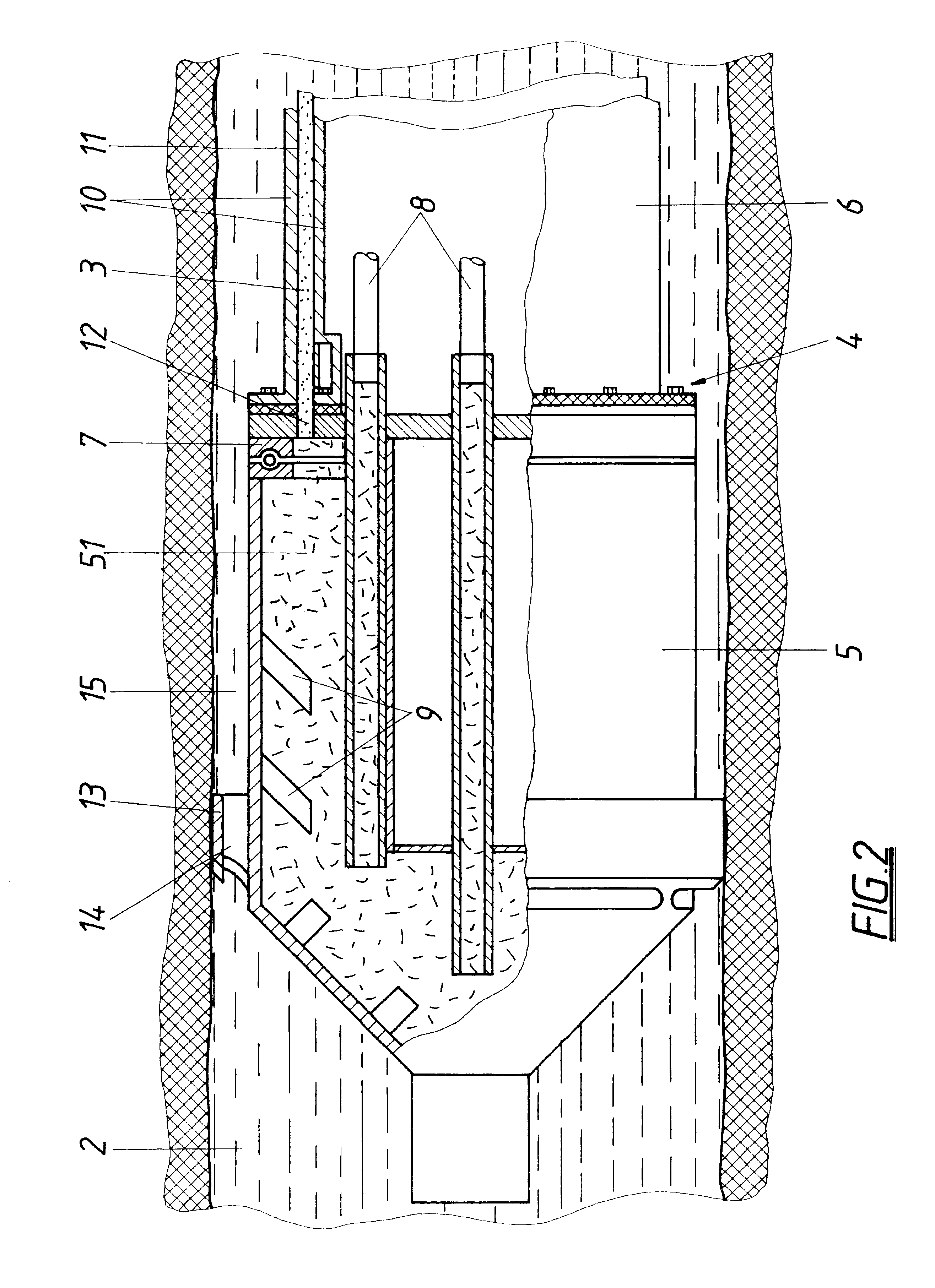
According to another embodiment of the invention an end piece which can be joined detachably to the calibrating cylinder belongs to the reactor. This end piece sealing off the calibrating space and exhibiting a ventilation device can be anchored torsionally in the inlet vicinity of the ground channel. The end piece facilitates initial forming of the run of piping, since it initially seals off the calibrating space and can be anchored torsionally at the ground channel inlet as the reactor is being inserted into the ground channel and at the correct height. The synthetic mass can now be prepared by impacting the reactor chamber with the synthetic constituents and pressed by raising the admission pressure in the calibrating space until the appearance of the synthetic mass from the ventilation device signals that the calibrating space is completely filled with synthetic mass. The connection between the end piece and the reactor can now be broken and the reactor drawn through the ground channel, whereby the run of piping, which has its beginning stuck in the end piece and remains torsionally anchored by way of the end piece, is extruded continuously, securely preventing the run of piping from twisting. Also, the height of the run of piping or of the pipe length required according to project can be adjusted geodetically precisely by means of the position of the end piece.
It is important here that any heat transfer from the calibrating cylinder to the reactor drum is prevented by corresponding insulation measures.

Problems solved by technology

The actual laying of the pipes is achieved by drawing a run of piping, made up of lengths of pipe, during the drawing procedure into the ground channel, which proves relatively expensive and time-consuming and requires large handling pits and surfaces.
In addition, the connection impacts of the pipe lengths always signify an increased risk of corrosion and fault point.

Method used


Image

  • Method and device for laying an underground duct made of a plastic material
  • Method and device for laying an underground duct made of a plastic material
  • Method and device for laying an underground duct made of a plastic material

Examples


Embodiment Construction

The object of the invention is therefore to indicate a process of the type described at the outset which permits efficient laying of underground piping, extensively disconnects fault points created by connection impact and also assists in minimising and variably shaping handling pits and surfaces, avoiding pipe insertion paths, reducing necessary transport and warehousing services and minimising as far as possible the demand for special dump sites for the discharged material and bore flushing, as well as required quantities of support fluid and the like. Also, an effective apparatus for carrying the process into effect is to be created.

The present invention solves this task by the piping, comprising a hardening synthetic mass, being manufactured at the same time as it is being introduced into the ground channel, in that the prepared synthetic mass is continuously formed inside the ground channel as a run of piping and left to harden. Accordingly, the run of piping is formed directly...


PUM

PropertyMeasurementUnit
Lengthaaaaaaaaaa

Abstract

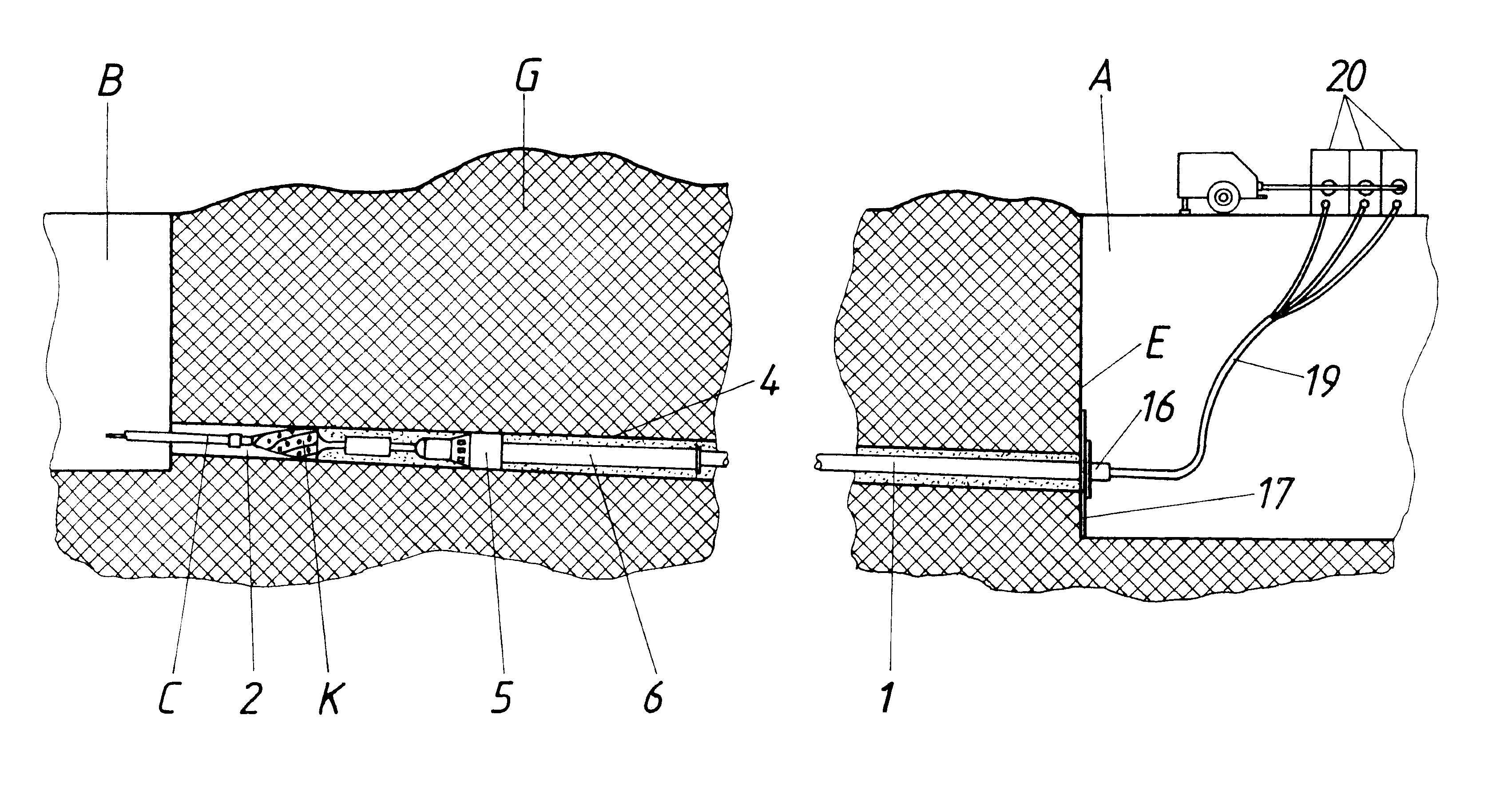
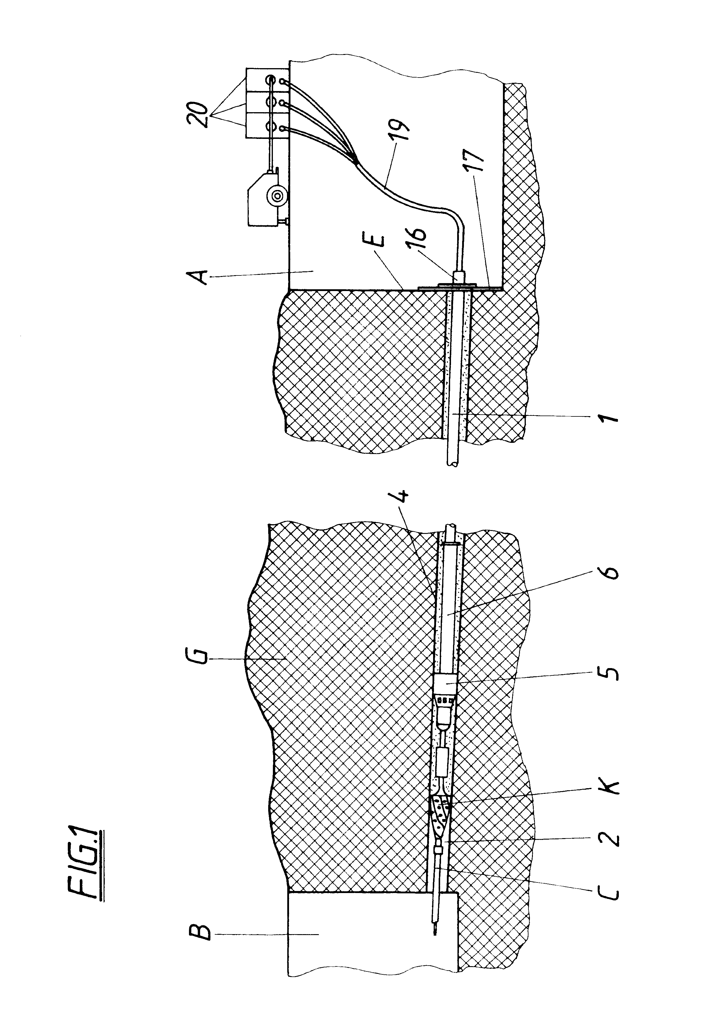
For laying synthetic underground piping (1) a ground channel (2) is first bored and the piping (1) is introduced into the ground channel (2). To facilitate laying an underground pipe length particularly effectively, the pipe length (1) comprising a hardening synthetic mass is manufactured at the same time as it is introduced into the ground channel (2) by the prepared synthetic mass being formed continuously inside the ground channel (2) as a run of piping (3) and left to harden. A reactor (4) which can be drawn through the ground channel (2) and comprising a front reactor drum (5) and a rear double-sheathed calibrating cylinder (6) is provided for this purpose, whereby reactor drum (5) and calibrating cylinder (6) are arranged coaxially to one another and relatively rotatably and lines (8) for supply of constituents terminate in the reactor chamber (51) of the reactor drum (5) and the reactor chamber (51) is connected by way of a nozzle ring (12) to the calibrating space, open from below and formed from the double mantle (10) of the calibrating cylinder (6).

Description

The present invention relates to a process for laying synthetic underground piping, according to which a ground channel is first bored and the piping introduced thereinto, as well as apparatus for carrying this process into effect.PRIOR ARTThere are various boring procedures, so-called horizontal boring procedures, already known for producing ground channels for subterranean laying of piping, wherein primarily bore flushing and a course-controlled bore head are employed which permit boring of corresponding ground channels along a piping course predetermined by a plan, with adequate accuracy of direction. These processes have thoroughly proven themselves, since they enable the laying of supply and sanitation piping in underground procedures with a minimum of necessary excavation work. The actual laying of the pipes is achieved by drawing a run of piping, made up of lengths of pipe, during the drawing procedure into the ground channel, which proves relatively expensive and time-consum...

Claims


Application Information

Patent Timeline
IPC IPC(8): B29B7/50B29B7/34B29C67/24E21B7/20B29C47/00E21D11/04F16L1/00
CPCB29B7/50E21B7/20B29C67/246B29L2023/22
Inventor LANDRICHTER, WOLFGANG
Owner LANDRICHTER WOLFGANG
Learn More