Eureka AIR delivers breakthrough ideas for toughest innovation challenges, trusted by R&D personnel around the world.

Apparatus and methods for treating bone

a bone and bone technology, applied in the field of surgical implants, can solve the problems of repositioning the fractured bone, not addressing the problem of spinal deformity, and limiting the treatment of compression fractures and related deformities, so as to increase the diameter of the coiled body, increase the space, and increase the radial

Active Publication Date: 2007-03-08
SYNTHES USA
View PDF40 Cites 157 Cited by
  • Summary
  • Abstract
  • Description
  • Claims
  • Application Information

AI Technical Summary

Benefits of technology

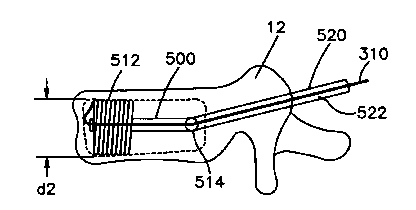
[0029] In an another embodiment a system for minimally invasive bone treatement, filling, augmenting, and / or reposition bone, may comprise an elongated body having a first end and a second end, the body having a length along its longitudinal axis, configured for implantation within a bone, and an insertion device for inserting the elongated body within a bone, the insertion device comprising a band and configured to cause the band to coil multiple times around the elongated body between the first and second end to increase the diameter of the body and band assembly, the insertion device releasably connectable to the body. The insertion device may comprise a drive line assembly to apply a rotational force to the elongated body to cause the elongated body to rotate about its longitudinal axis to coil the band around the elongated body, to increase the diameter of the elongated body and band assembly implanted within the region of bone.
[0047] In other embodiments, minimally invasive implants for distracting spine segments include a coiled body having a first diameter dimensioned for implantation in a space between two or more vertebral features, wherein the coiled body is configured to uncoil to a second diameter that is larger than the first diameter, and thereby increase the space between the two or more vertebral features.

Problems solved by technology

Until recently, doctors were limited in how they could treat such compression fractures and related deformities.
However, this procedure may not reposition the fractured bone and therefore may not address the problem of spinal deformity due to the fracture.
Moreover, this procedure requires high-pressure cement injection using low-viscosity cement, and may lead to cement leaks in 30-80% of procedures, according to recent studies.
In rare cases, however, polymethymethacrylate or other cement leaks into the spinal canal or the perivertebral venous system and causes pulmonary embolism, resulting in death of the patient.
Disadvantages of this procedure include the high cost, the repositioning of the endplates of the vertebral body are lost after the removal of the balloon catheter, and the possible perforation of the vertebral endplates during the procedure.
Such a cement leak may occur through the low resistance veins of the vertebral body or through a crack in the bone which had not been appreciated previously.
The cement may be forced into the low resistance venous system and travel to the lungs or brain resulting in a pulmonary embolism or stroke.
One drawback of this system, however, is that the mesh implant is not well integrated in the vertebral body.
This can lead to relative motion between the implant and vertebral body, and consequently to a postoperative loss of reposition.

Method used


Image

  • Apparatus and methods for treating bone
  • Apparatus and methods for treating bone
  • Apparatus and methods for treating bone

Examples


Embodiment Construction

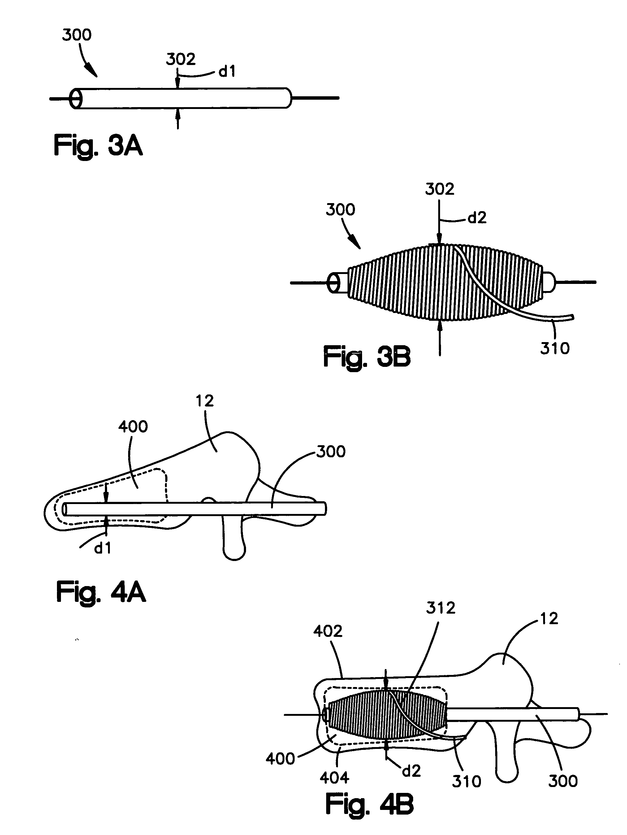
[0105] A vertebral body may be filled, augmented, or repositioned through insertion of one or more implants into an internal portion of the vertebral body, between the endplates of two adjacent vertebral bodies, or in other bone, e.g., a femur. In one embodiment, a vertebral body implant may comprise a bobbin with a thread, string, or wire, collectively referred to herein as a band 310, coiled around the bobbin to create a larger diameter mass or body, sometimes referred to as a coiled assembly, coiled band assembly, coiled body, final implant, or implant. The bobbin with the attached band may be inserted into the vertebral body through, for example, transpedicular access canals having a diameter of about 5 mm.

[0106] Referring to FIG. 3A, an elongated member 300, which may be cylindrical and is hereinafter referred to as a bobbin 300, has a certain diameter d1302. After insertion of bobbin 300 into a collapsed vertebral body, band 310 is coiled around bobbin 300 to create a larger ...


PUM


Abstract

Implants and methods for bone treatment, preferably minimally invasive treatment, including repositioning of vertebrae may comprise insertion of a bobbin having a wire, string, thread or band, coiled around the bobbin. During coiling, the diameter of the bobbing / band complex may increase. Such increase in diameter can push against the inner side of the endplates of the vertebral body, and augment the vertebral body to its original height. The implant may also take the form of a coiled sleeve which when inserted into the vertebral body is uncoiled. The force of the uncoiling sleeve pushes against the inner side o the endplates of the vertebral body, restoring the vertebral body to its original height. The implant may also take the form of fibrous masses comprised of a thread or other relatively thin structure, for example a fiber or strand, of any biocompatible material having desired characteristics, for example a shape memory alloy, titanium, stainless steel, another metal or metal alloy, a ceramic, a composite or any combination thereof. The, strand, thread or other fiber may be coiled, woven, matted, tangled or otherwise formed into a wool-like mass or body having a desired configuration. Expansion of the expandable member within the vertebral body or other bone may reposition the fractured bone to a desired height and augment the bone to maintain the desired height. A bone cement or other filler can be added to further treat and stabilize the vertebral body or other bone.

Description

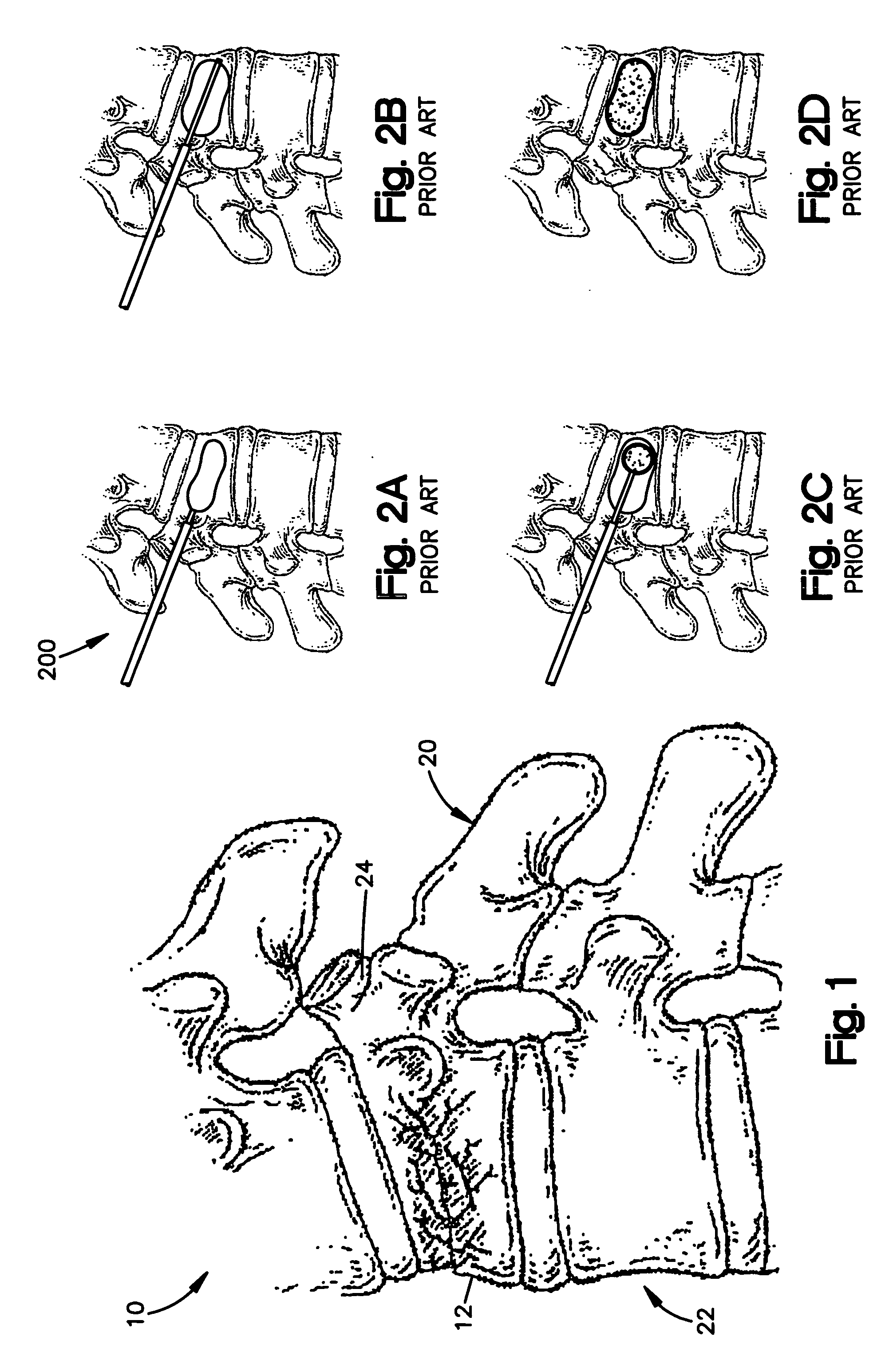
CROSS REFERENCE E TO RELATED APPLICATIONS [0001] The present application claims priority to U.S. Provisional Application Nos. 60,692,408 filed Jun. 20, 2005; 60,715,188 filed Sep. 8, 2005; and 60,733,647 filed Nov. 4, 2005, the entire content of which are expressly incorporated herein by reference thereto.FIELD OF THE INVENTION [0002] The invention relates to surgical implants, and more particularly to minimally invasive apparatus and methods for treating (filling, augmenting, and / or reposition bone) bone, preferably vertebrae and / or restoring spinal lordosis. BACKGROUND OF THE INVENTION [0003] Vertebral compression fractures, as illustrated in FIG. 1, represent a generally common spinal injury and may result in prolonged disability. F. Margerl et al: A comprehensive classification of thoracic and lumbar injuries, Eur Spine J 184-201, 1994. These fractures involve collapsing of one or more vertebral bodies 12 in the spine 10. Compression fractures of the spine usually occur in the l...

Claims


Application Information

Patent Timeline
Patent Type & Authority Applications(United States)
IPC IPC(8): A61B17/58
CPCA61B17/7062A61B17/7095A61B2017/0256A61B17/8852A61B17/8858A61B17/742A61B17/56A61B17/58
Inventor APPENZELLER, ANDREASDUTOIT, CHRISTOFBENOIT, ALFREDSTOLL, THIERRYROTHLISBERGER, ERICHMATHYS, STEFAN
Owner SYNTHES USA
Why Eureka
Eureka Blog
Learn More