Ultrasonic doppler flow-meter

a flow-meter and ultrasonic technology, applied in the direction of measuring devices, instruments, fluid speed measurement, etc., can solve the problems of reducing the accuracy of the laser-type sensor, affecting the accuracy of the measurement, and the inability to use the laser-type sensor in opaque media,

Inactive Publication Date: 2003-05-20
TODA KOHJI
View PDF9 Cites 15 Cited by
  • Summary
  • Abstract
  • Description
  • Claims
  • Application Information

AI Technical Summary

Benefits of technology

Another object of the present invention is to provide an ultrasonic Doppler flow-meter excellent in measurement accuracy, response time, durability, and manufacturing.
A still other object of the present invention is to provide an ultrasonic Doppler flow-meter easy in use and having a small size which is very light in weight and has a simple structure.

Problems solved by technology

These touch-type devices have some problems on measurement accuracy, response time, difficulty in use, durability and manufacturing.
The laser-type sensor has a defect that the longer the length of the laser beam, the lower the measurement accuracy because of flickering of the laser beam itself.
In addition, the use of the laser-type sensor is impossible for the measurement in opaque media.
The electroacoustic-type sensor has some problems on measurement accuracy, resistance for a change of circumstances, and so on.
In addition, it is difficult to measure precisely and conveniently a flowing speed of a liquid by conventional devices.

Method used


Image

  • Ultrasonic doppler flow-meter
  • Ultrasonic doppler flow-meter
  • Ultrasonic doppler flow-meter

Examples


first embodiment

FIG. 8 shows a diagram of signal analyzing unit 4 according to a Signal analyzing unit 4 comprises signal generator 8, amplifier 9 and frequency counter 10.

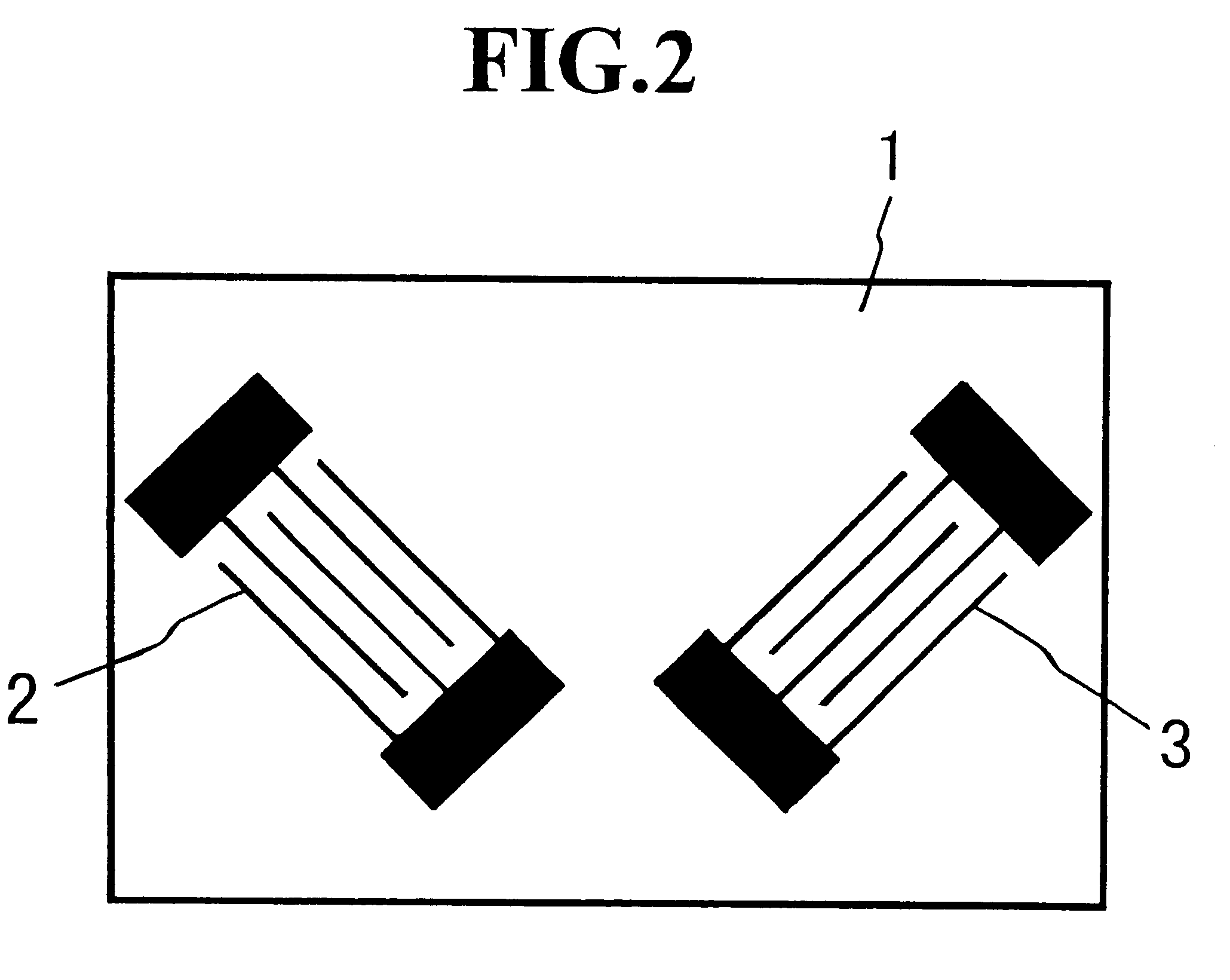
In the ultrasonic Doppler flow-meter in FIG. 1 having signal analyzing unit 4 in FIG. 3, if an input electric signal with a carrier frequency f.sub.0 approximately corresponding to the interdigital periodicity of input interdigital transducer 2, is applied from signal generator 8 to input interdigital transducer 2, a leaky Lamb wave is excited in substrate 1. Because substrate 1 is made of a piezoelectric ceramic plate, and in addition, the polarization axis thereof is parallel to the thickness direction thereof, the leaky Lamb wave is excited in substrate 1 effectively. The leaky Lamb wave having the wavelength approximately equivalent to the interdigital periodicity is radiated effectively in the form of a longitudinal wave into the liquid, in other words, a mode conversion from the leaky Lamb wave to the longitudinal wave in ...

second embodiment

FIG. 10 shows a diagram of signal analyzing unit 4 according to a Signal analyzing unit 4 comprises signal generator 11, amplifier 12 and frequency to voltage (F / V) converter 13.

In the ultrasonic Doppler flow-meter in FIG. 1 having signal analyzing unit 4 in FIG. 10, if an input electric signal with a carrier frequency f.sub.0 is applied from signal generator 11 to input interdigital transducer 2, a leaky Labm wave is excited in substrate 1. The leaky Lamb wave is radiated in the form of a longitudinal wave into the liquid. Then, disk 6 reflects the longitudinal wave in the liquid. The reflected longitudinal wave is detected at output interdigital transducer 3 as a delayed electric signal with a Doppler frequency f. The delayed electric signal is amplified via amplifier 12. The amplified electric signal is transmitted to F / V converter 13, which converts the Doppler frequency f to a voltage thereof and detects the frequency difference .DELTA.f in terms of the voltage converted from ...

third embodiment

FIG. 11 shows a diagram of signal analyzing unit 4 according to a Signal analyzing unit 4 comprises signal generator 14, attenuator 15, phase shifter 16, and phase comparator 17.

In the ultrasonic Doppler flow-meter in FIG. 1 having signal analyzing unit 4 in FIG. 11, if an input electric signal with a carrier frequency f.sub.0 is applied from signal generator 14 to input interdigital transducer 2, a leaky Lamb wave is excited in substrate 1. The leaky Lamb wave is radiated in the form of a longitudinal wave into the liquid. Then, disk 6 reflects the longitudinal wave in the liquid. The reflected longitudinal wave is detected at output interdigital transducer 3 as a delayed electric signal with a Doppler frequency f. A phase of the delayed electric signal is compared with that of the input electric signal at phase comparator 17. In this time, the phase of the input electric signal attenuated via attenuator 15, in case of no rotation of disk 6, is controlled to be coincident with tha...


PUM


Abstract

An ultrasonic Doppler flow-meter comprises a substrate with a piezoelectricity, input- and output interdigital transducers formed on a first end surface of the substrate, and a signal analyzing unit connected between the input- and output interdigital transducers. A second end surface of the substrate is in contact with a liquid. The finger direction the output interdigital transducer is slanting to that of the input interdigital transducer. When an input electric signal with a carrier frequency f0 is applied to the input interdigital transducer, a leaky Lamb wave is excited in the substrate. The leaky Lamb wave is radiated into the liquid in the form of a longitudinal wave, which is reflected back by a material in the liquid. The reflected longitudinal wave is detected at the output interdigital transducer as a delayed electric signal with a Doppler frequency f. A moving speed of the material is sensed at the signal analyzing unit in terms of a frequency difference DELTAf between the carrier frequency f0 and the Doppler frequency f.

Description

1. Field of the InventionThe present invention relates to an ultrasonic device for measuring a flowing speed of a liquid or a material's moving speed in a liquid by making use of the Doppler effect.2. Description of the Prior ArtThere are touch- and untouch-types of conventional devices for detecting a vibration displacement. Devices, for example, as an electric micrometer and a digital gauge for a small displacement, a rotary encoder for a rotation displacement, and a linear scale for a large displacement belong to the touch-type. These touch-type devices have some problems on measurement accuracy, response time, difficulty in use, durability and manufacturing. Devices, for example, as a laser-type sensor and an electroacoustic-type sensor belong to the untouch-type. The laser-type sensor has a defect that the longer the length of the laser beam, the lower the measurement accuracy because of flickering of the laser beam itself. In addition, the use of the laser-type sensor is impos...

Claims


Application Information

Patent Timeline
Patent Type & Authority Patents(United States)
IPC IPC(8): G01F1/66G01P5/00
CPCG01F1/663
Inventor TODA, KOHJI
Owner TODA KOHJI
Why Eureka
Try Eureka