
Computer-based system for producing multi-color multilayer images on substrates using dry multi-colored cholesteric liquid crystal (CLC) pigment materials applied to binder material patterns

a computer-based system and multi-layer image technology, applied in the field of painting and image printing, can solve the problems of limiting the system from being able to be expanded, unable to handle colorants with relatively large pigment particles, and unable to achieve the effect of enhancing the functionality of the printing device, and enhancing the flexibility of the printing devi

Inactive Publication Date: 2003-02-04
REVEO
View PDF35 Cites 16 Cited by
  • Summary
  • Abstract
  • Description
  • Claims
  • Application Information

AI Technical Summary

Benefits of technology

One objective of this invention is to improve today's printing technologies. The inventors of the present invention have developed a new printing technology that offers a simple system configuration, greater flexibility, improved printing quality, and enhanced functionality. The new technique is termed Dry Printing Technology (DPT) by its working principle. It uses only one printing head and prints images with an invisible ink. It can handle, in principle, all kinds of colorants, even colorants with larger pigments so that it removes the pigment size constraint in ink jet nozzle printing. By adopting a new printing head combined with CLC pigments, dry printing offers enhanced image quality. Finally, DPT can be easily expanded to print a colorful picture in 3-D with the CLC pigments.
Yet another objective is to give printing devices more flexibility and enhance their functionality.

Problems solved by technology

This forces the printing system to become mechanically complex and limits the system from being able to be expanded to serve multiple functions such as the case of 3-D printing.
In addition, since the printing nozzles and screens have a very fine apertures, they can't handle those colorants with relatively larger pigment particles.
As a result, CLC has never been practically used in real artwork or other applications.

Method used


Image

  • Computer-based system for producing multi-color multilayer images on substrates using dry multi-colored cholesteric liquid crystal (CLC) pigment materials applied to binder material patterns
  • Computer-based system for producing multi-color multilayer images on substrates using dry multi-colored cholesteric liquid crystal (CLC) pigment materials applied to binder material patterns
  • Computer-based system for producing multi-color multilayer images on substrates using dry multi-colored cholesteric liquid crystal (CLC) pigment materials applied to binder material patterns

Examples


Embodiment Construction

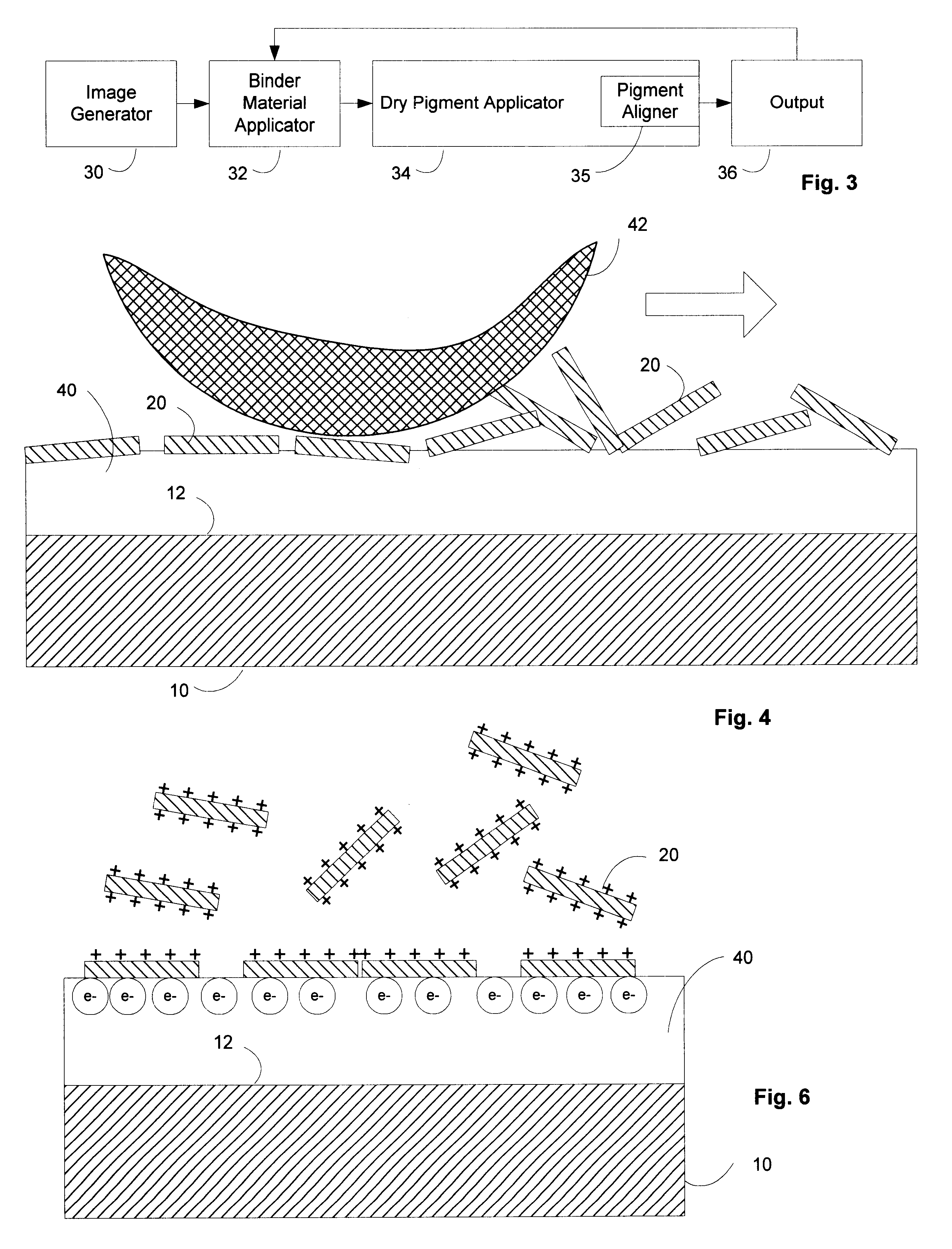
The present invention, termed "Dry Printing Technology" (DPT), enables many new applications to surface. The central part of the new technology is to print an image with an optically clear ink through a single printing head followed by an applying of CLC pigments.

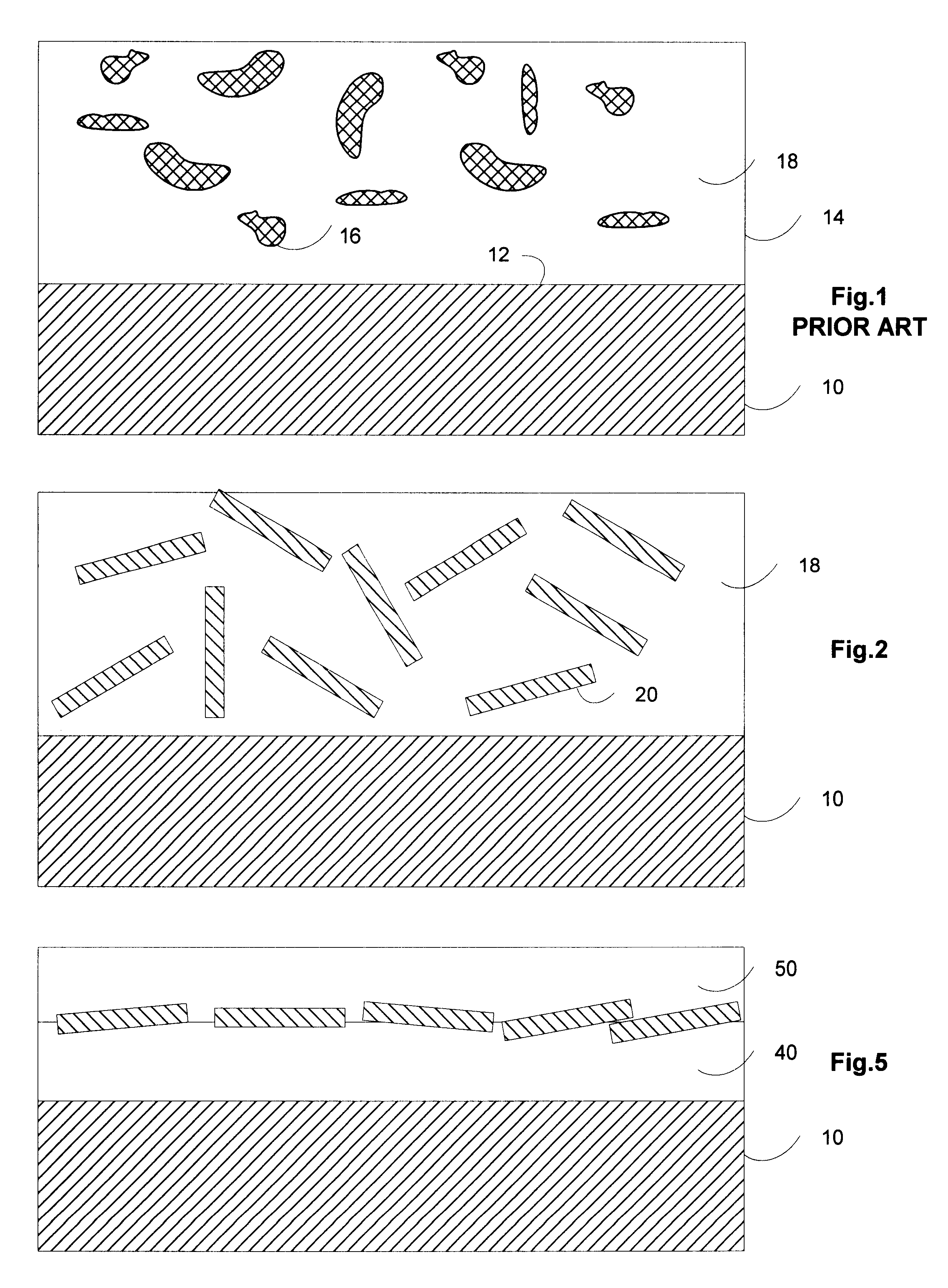
FIG. 1 shows an object 10 having a surface 12 covered with a prior art "paint layer" 14. The paint layer 14 generally comprises pigment particles 16 dispersed in a binder material 18.

FIG. 2 shows a paint layer like FIG. 1 where the pigment material is in the form of flakes 20. The flakes 20 are shown randomly dispersed in the binder material 18. For reflective non metallic pigment particles like CLC flakes, multilayer polymer material flakes, or inorganic multilayer material flakes which have reflectivity by virtue of the interference effect of light reflection from a spatially varying index of refraction, the angle of viewing is critical, and no coherent effect is gained when the eye sees a large collection of pigment part...


PUM


Abstract

A computer-based system for producing a multi-color multilayer image on a substrate using multi-colored cholesteric liquid crystal (CLC) pigment materials made from CLC flakes tuned to predetermined bands of color. A computer-controlled image generator automatically generates an image specifying a pattern over which binder material is to be applied to a substrate by a binder material applicator. A plurality of CLC pigment applicators automatically apply patterns of different-color CLC pigment material to a pattern of binder material applied to the substrate, binding thereto as the binder material dries. An output device is used to automatically return the substrate to a different one of CLC pigment applicators after each application of a pattern of different-color CLC pigment material to the pattern of binder material. The output device automatically repeats the return of the substrate to the CLC pigment applicators until all bands of color in the multi-color multilayer image are rendered and the multi-color multilayer image is produced.

Description

1. Field of InventionThis document describes a technology for painting and image printing that utilizes a simple system with multiple colorants and a single printing head through which the image is printed by a transparent ink or binder. The primary area of interest involves dry pigments of larger molecular weight colorants, such as cholesteric liquid crystal (CLC) pigments, and their diverse applications in modern printing and painting. In addition, new techniques can be easily expanded to serve more functions, such as 3-D stereoscopic image capability.2. Brief Description of the LiteratureBroadband reflecting polarizers were introduced in application Ser. No. 08 / 550,022 (now U.S. Pat. No. 5,691,789) entitled "Single Layer Reflective Super Broadband Circular Polarizer and Method of Fabrication Therefor" by Sadeg M. Faris and Le Li which was filed Oct. 30, 1995. Such broadband polarizers are made by producing a single layer having cholesteric liquid crystal order where the pitch of ...

Claims


Application Information

Patent Timeline
IPC IPC(8): B41M3/00G02B5/30G03G9/09B41M3/14
CPCB41M3/00B41M3/148G02B5/3016G03G9/09G03G9/0926G03G9/0906B41M3/14Y10T428/24942Y10T428/254Y10T428/239Y10T428/232B05D1/06
Inventor JIANG, YINGQIULI, LEFARIS, SADEG
Owner REVEO
Learn More