
Electric machine monitoring method and system

Inactive Publication Date: 2002-12-17
GENERAL ELECTRIC CO
View PDF12 Cites 30 Cited by
  • Summary
  • Abstract
  • Description
  • Claims
  • Application Information

AI Technical Summary

Benefits of technology

Problems in the combination of the traction motor and wheel set of a locomotive which are related to gears (insufficient lubrication due to oil-loss, gear wear, or cracks, for example) and bearings (damaged bearings or loss of lubrication, for example) are reflected in the torque of the motor. Under substantially constant operating conditions (that is, the rotational direction does not change and neither the rotational speed nor the load deviates by more than about 5%), such problems lead to substantially periodic add

Problems solved by technology

Problems in the combination of the traction motor and wheel set of a locomotive which are related to gears (insufficient lubrication due to oil-loss, gear wear, or cracks, for example) and bearings (damaged bearings or loss of lubrication, for example) are reflected in the torque of the motor.
Under substantially constant operating conditions (that is, the rotational direction does not change and neither the rotational speed nor the load deviates by more than about 5%), such problems lead to substantially periodic additive components of the torque which are not present for a healthy motor.

Method used


Image

  • Electric machine monitoring method and system
  • Electric machine monitoring method and system
  • Electric machine monitoring method and system

Examples


example 1

In Example 1, two sets of signals correspond to two different levels of wear, and a linear combination of low-level features which is an optimal discriminator between the two sets is determined by using a Fisher linear discriminant method such as described in R. O. Duda & P. E. Hart, Pattern Classification and Scene Analysis, Wiley, 1973, for example.

In particular, y.sub.j =(Y.sub.jl, . . . , Y.sub.jM).sup.T represent the low level feature vectors of the data sets in the low wear level set, and z.sub.j =(z.sub.jl, . . . , z.sub.jM).sup.T represent the corresponding feature vectors of the high wear level set. Then the linear function ##EQU1##

for which ##EQU2##

is maximum is the Fisher linear discriminant. In this example, a=(a.sub.l, . . . , a.sub.M).sup.T is a parameter vector which represents the weights in the optimal linear combination of low-level features, ##EQU3##

is the sample mean of the feature vectors in the first set with N.sub.y being the number of low wear level data sets...

example 2

In Example 2, determining the low level discriminator functions comprises using multiple regression of at least three sets of features indicative of at least three different machine conditions (at substantially constant rotational speed, load, and direction) to determine a combination of the low level features of the at least three sets of features which is an optimal discriminator. In one example of this embodiment, the training data corresponds to three or more levels of wear. In particular, it is assumed that feature vector y.sub.j corresponds to the level of wear w.sub.j, and a coefficient vector a and a constant .beta. are determined such that

a.sup.T y.sub.j +.beta.=W.sub.j for all j,

in the least squares sense. This corresponds to choosing a direction a and providing the axis in direction a with its own scale and origin such that the projection of a feature vector x onto that axis is a good estimate, in the least squares sense, of the associated level of wear w.

FIG. 8 is a grap...

examples 1 and 2

are described for purposes of example only. Other appropriate learning or training techniques may be used for constructing a mapping from the low-level feature space to the indicator value or to the low dimensional high level feature space, and also from the high level feature space to the indicator value. Several examples are neural networks, nearest neighbor classification, fuzzy inference system, principal component analysis, and Bayesian based approaches and other parametric methods.

In one embodiment, the steps of obtaining signals, identifying low level features, and obtaining indicator values (whether directly from low level features or from high level features derived from low level features) are repeated, and a representation (such as a curve, for example) of machine condition degradation as a function of time is formed. The representation can be used to monitor the rate of change of degradation and / or to estimate time remaining prior to reaching a critical threshold.

Thus, w...


PUM


Abstract

A machine monitoring method includes obtaining signals indicative of machine conditions, machine rotational speed, direction, and load conditions over a segment of time, transforming the obtained signal indicative of machine conditions into a frequency spectrum, identifying low level features of the frequency spectrum, and processing the low level features to obtain an indicator value representative of the machine conditions.

Description

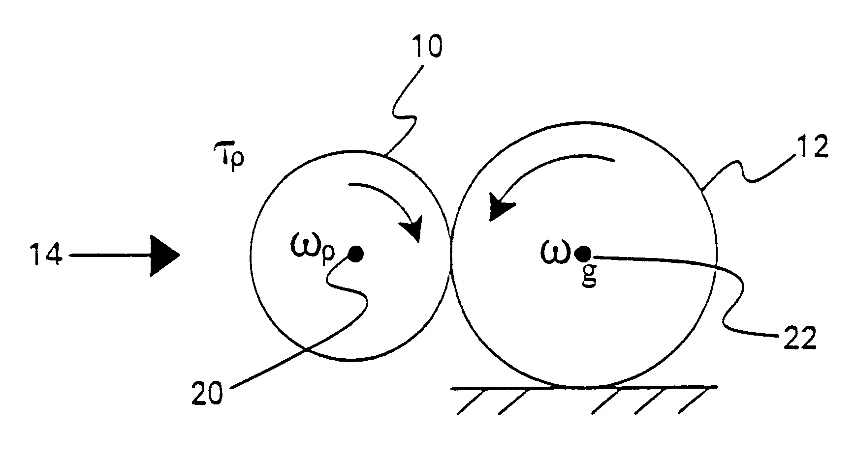
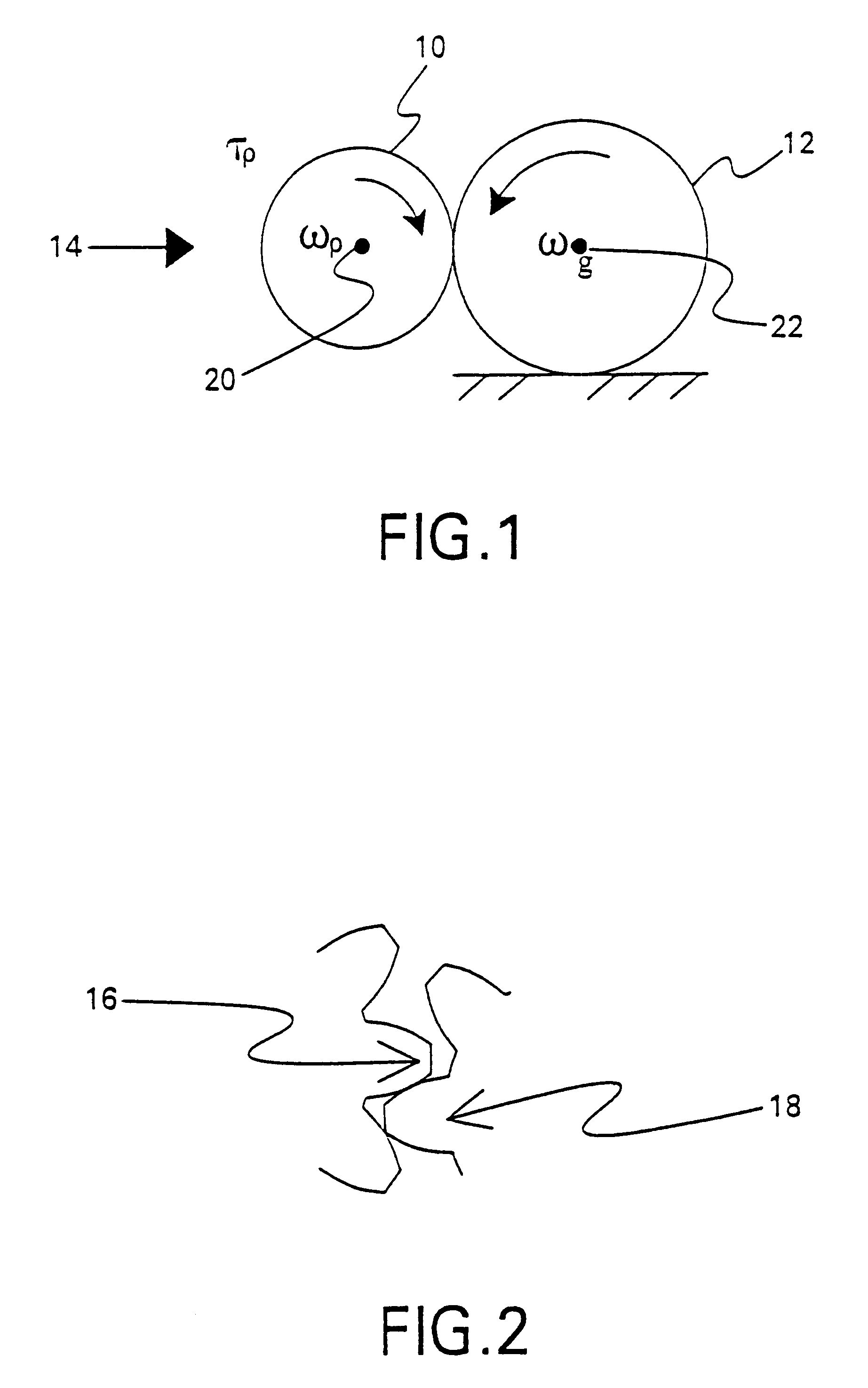
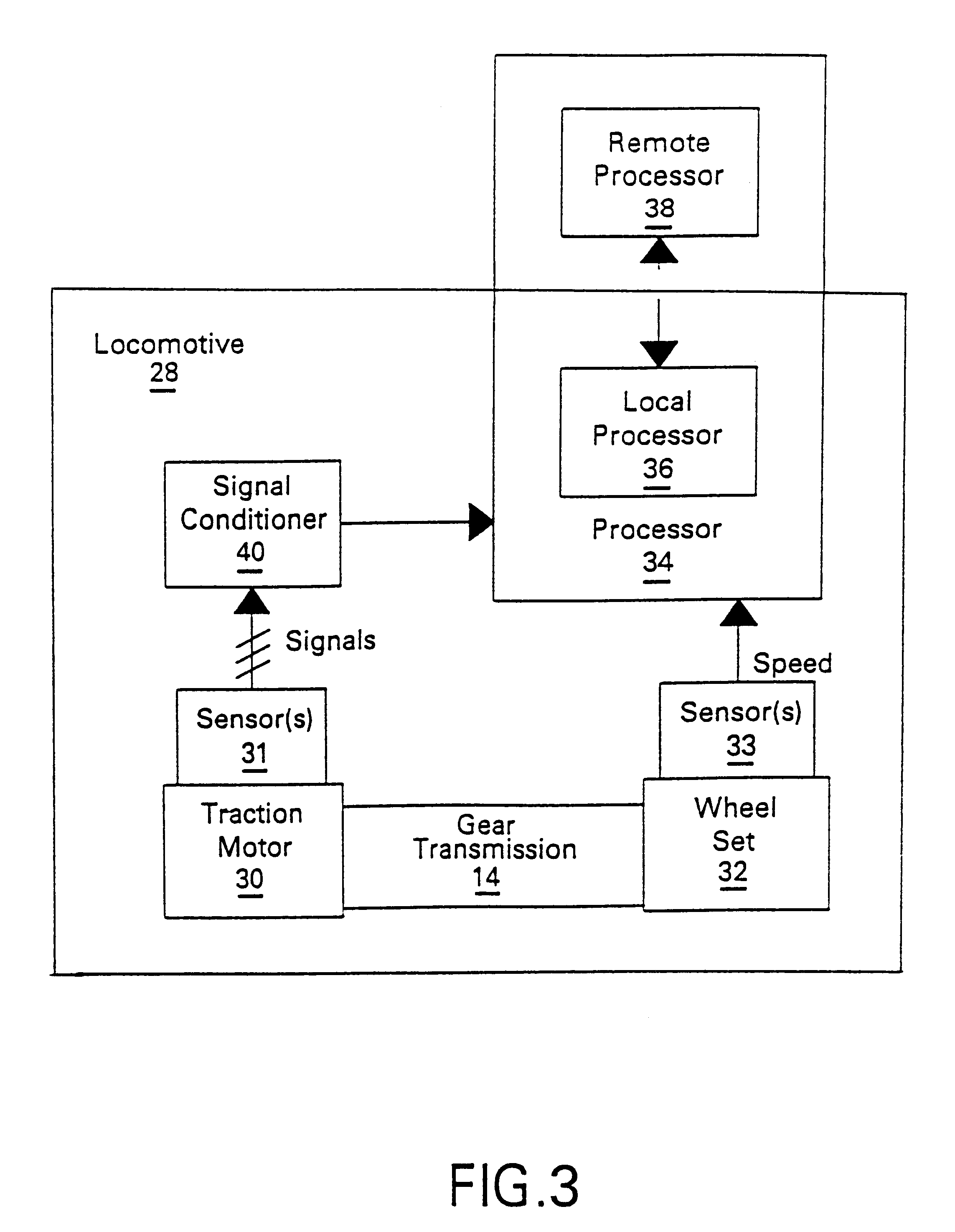
The invention relates generally to electric machine monitoring and more particularly to gear and bearing monitoring.Locomotive traction systems include traction motors, gears, axles, wheel-sets, and bearings. The gears are often lubricated with oil, and the pinion gear is sometimes fitted onto the traction motor shaft using an interference or shrink fit. In some situations, the oil in a gear case also lubricates motor bearings through a passage from the gear case to the bearings. There are several failures that can result in gear problems, including, for example, cracks in gear teeth due to excessive loading and loss of lubrication resulting in gear teeth wear. Loss of lubrication and / or gear problems can lead to gear damage, slipping of pinion gear on the motor shaft, and / or damage to bearings from vibrations that result in motor failures, and ultimately road failures. Prevention of serious gear, bearing, motor and road failures through incipient failure detection would therefore b...

Claims


Application Information

Patent Timeline
IPC IPC(8): G05B23/02
CPCG05B23/0221
Inventor CLAUS, BERNHARD ERICH HERMANNKLIMAN, GERALD BURTCHBAT, NICOLAS WADIH
Owner GENERAL ELECTRIC CO
Learn More